Lexus NX: Components
COMPONENTS
ILLUSTRATION
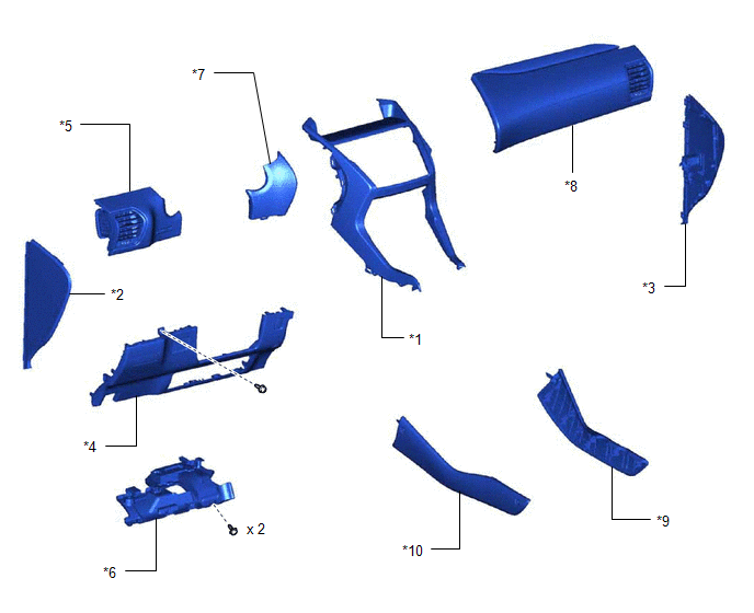
| *1 | CENTER INSTRUMENT CLUSTER FINISH PANEL ASSEMBLY | *2 | INSTRUMENT SIDE PANEL LH |
| *3 | INSTRUMENT SIDE PANEL RH | *4 | LOWER NO. 1 INSTRUMENT PANEL FINISH PANEL |
| *5 | NO. 1 INSTRUMENT PANEL SAFETY PAD SUB-ASSEMBLY | *6 | NO. 1 INSTRUMENT PANEL UNDER COVER SUB-ASSEMBLY |
| *7 | NO. 1 SWITCH HOLE BASE | *8 | NO. 2 INSTRUMENT PANEL SAFETY PAD SUB-ASSEMBLY |
| *9 | UPPER NO. 1 CONSOLE PANEL GARNISH | *10 | UPPER NO. 2 CONSOLE PANEL GARNISH |
ILLUSTRATION
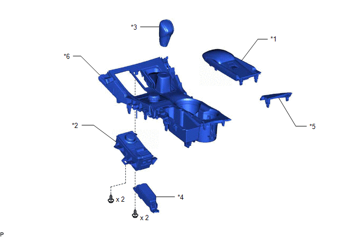
| *1 | CONSOLE ARMREST ASSEMBLY | *2 | INTEGRATION CONTROL AND PANEL ASSEMBLY (ELECTRIC PARKING BRAKE SWITCH) |
| *3 | SHIFT LEVER KNOB SUB-ASSEMBLY | *4 | SHIFT POSITION INDICATOR |
| *5 | UPPER REAR CONSOLE PANEL | *6 | UPPER REAR CONSOLE PANEL SUB-ASSEMBLY |
READ NEXT:
 Removal
REMOVAL PROCEDURE 1. REMOVE CONSOLE ARMREST ASSEMBLY Click here 2. REMOVE UPPER REAR CONSOLE PANEL Click here 3. REMOVE UPPER NO. 2 CONSOLE PANEL GARNISH Click here 4. REMOVE UPPER NO. 1 CON
Inspection
INSPECTION PROCEDURE 1. INSPECT INTEGRATION CONTROL AND PANEL ASSEMBLY (ELECTRIC PARKING BRAKE SWITCH) (a) Measure the resistance according to the value(s) in the table below. Standard Resistance:
Installation
INSTALLATION PROCEDURE 1. INSTALL INTEGRATION CONTROL AND PANEL ASSEMBLY (ELECTRIC PARKING BRAKE SWITCH) (a) Install the integration control and panel assembly (electric parking brake switch) to th
SEE MORE:
Startability Malfunction (P1604)
DESCRIPTION If the engine does not start or it takes a long time for the engine to start, despite the ECM receiving the engine start request signal from the hybrid vehicle control ECU via CAN communication, this DTC will be stored. Read freeze frame data using the Techstream. The ECM records vehicle
Rear Power Window LH Auto Up / Down Function does not Operate with Rear Power Window Switch LH
DESCRIPTION If the manual up and down function operates normally but the auto up and down function does not, then fail-safe mode may be functioning. If power window initialization has not been performed, the auto up and down function will not operate. Click here WIRING DIAGRAM CAUTION / NOTICE /
© 2016-2026 Copyright www.lexunx.com
