Lexus NX: Removal
REMOVAL
PROCEDURE
1. REMOVE NO. 1 SPEAKER WITH BOX ASSEMBLY (w/ ASC System)
Click here .gif)
2. REMOVE REAR CONSOLE BOX ASSEMBLY (w/o ASC System)
Click here
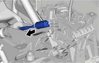
3. DISCONNECT TRANSMISSION CONTROL CABLE ASSEMBLY
(a) Move the shift lever to N.
| (b) Disconnect the end of the transmission control cable assembly from the shift lever assembly. |
|
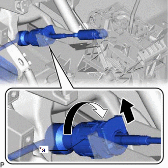
| (c) Rotate the nut of the transmission control cable assembly clockwise approximately 180° and, while holding the nut in that position, disconnect the transmission control cable assembly from the shift lever assembly. NOTICE: Do not over-rotate the nut as it will come off the internal spring and the transmission control cable assembly will not be reusable. |
|
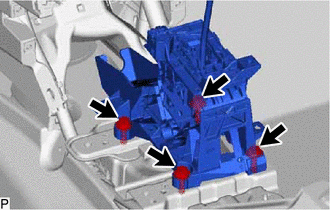
4. REMOVE SHIFT LEVER ASSEMBLY
| (a) Disconnect the transmission control switch connector. |
|
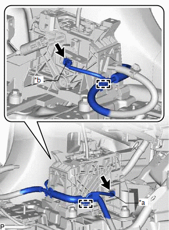
(b) Disconnect the shift lock control ECU connector.
(c) Disconnect the 2 clamps from the shift lever assembly.
| (d) Remove the nut from the shift lever assembly. |
|
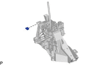
| (e) Remove the 4 bolts and shift lever assembly from the body. |
|
READ NEXT:
 Disassembly
DISASSEMBLY PROCEDURE 1. REMOVE SHIFT LEVER CAP (a) Using a screwdriver with its tip wrapped with protective tape, detach the 2 claws and remove the shift lever cap from the shift position indicato
Inspection
INSPECTION PROCEDURE 1. INSPECT SHIFT LOCK CONTROL ECU (a) Measure the voltage according to the value(s) in the table below. Standard Voltage: Tester Connection Condition Specified Conditio
Reassembly
REASSEMBLY PROCEDURE 1. INSTALL SHIFT POSITION INDICATOR (a) Install the shift position indicator to the rear upper console panel sub-assembly with the 2 screws. 2. INSTALL SHIFTING HOL
SEE MORE:
Cold Start Ignition Timing Performance (P050B)
MONITOR DESCRIPTION This monitor will run when the engine is started at an engine coolant temperature of -10 to 50°C (14 to 122°F). The DTC is stored after the engine idles for 13 seconds (2 trip detection logic). The DTC is designed to monitor the ignition timing at cold start. When the engine is
Parts Location
PARTS LOCATION ILLUSTRATION *A w/ Panoramic View Monitor System *B w/ Parking Assist Monitor System *1 BLIND SPOT MONITOR SENSOR LH (MASTER) *2 BLIND SPOT MONITOR SENSOR RH (SLAVE) *3 OUTER MIRROR CONTROL ECU ASSEMBLY LH *4 OUTER MIRROR CONTROL ECU ASSEMBLY RH *5
