Lexus NX: Diagnosis System
DIAGNOSIS SYSTEM
PARKING ASSIST MONITOR DIAGNOSIS SYSTEM
(a) For panoramic view monitor system diagnosis, signals received by the parking assist ECU can be checked, and the panoramic view monitor system can be calibrated, adjusted and checked using the multi-display assembly.
NOTICE:
Depending on the parts that are replaced or operations that are performed during vehicle inspection or maintenance, calibration of other systems as well as the panoramic view monitor system may be needed.
Click here .gif)
HINT:
The displayed screens and items may differ depending on vehicle specifications.
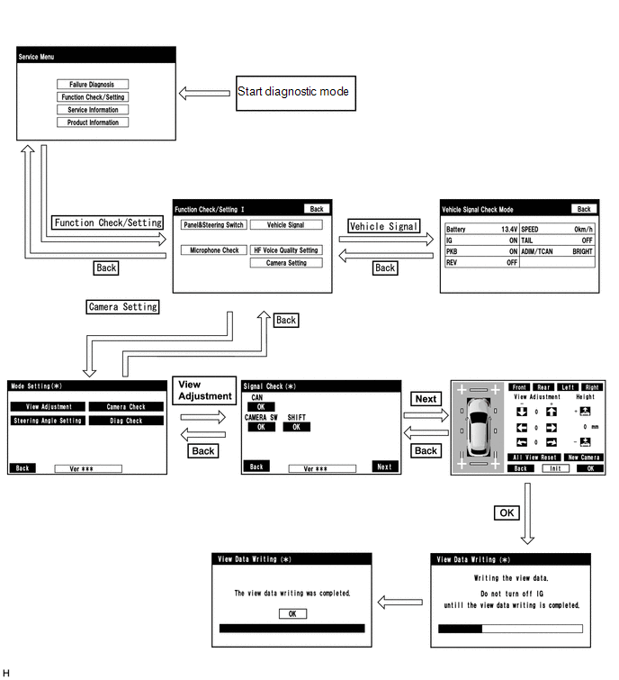
DIAGNOSIS SCREEN TRANSITION (VIEW ADJUSTMENT)
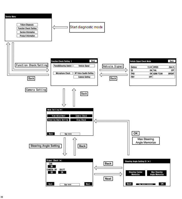
DIAGNOSIS SCREEN TRANSITION (STEERING ANGLE SETTING)
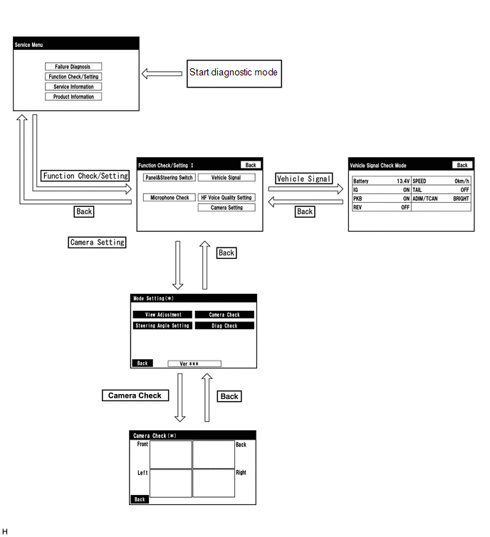
DIAGNOSIS SCREEN TRANSITION (CAMERA CHECK)
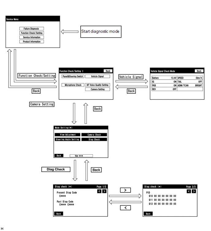
DIAGNOSIS SCREEN TRANSITION (DIAG CHECK)
DIAGNOSTIC MODE
(a) Diagnostic mode
-
w/ Audio and Visual System:
Click here
-
w/ Navigation System:
Click here
(b) Failure diagnosis
-
w/ Audio and Visual System:
Click here
-
w/ Navigation System:
Click here
(c) System check (check using system check mode screen)
-
w/ Audio and Visual System:
Click here
-
w/ Navigation System:
Click here
(d) Finish diagnostic mode.
-
w/ Audio and Visual System:
Click here
-
w/ Navigation System:
Click here
Diag Check
(a) Start diagnostic mode.
-
w/ Audio and Visual System:
Click here
-
w/ Navigation System:
Click here
.png)
(1) Select "Function Check/Setting" on the "Service Menu" screen.
.png)
(2) Select "Camera Setting" on the "Function Check/Setting I" screen.
NOTICE:
If the "Camera Setting" selection screen is not displayed, turn the power switch off and enter the diagnosis screen after turning the power switch on (IG) once again.
.png)
(3) Select "Diag Check" on the "Mode Setting" screen to display the "Diag Check" screen.
HINT:
To select a grayed out item, select and hold the item for 2 seconds or more.
(b) Check Diagnosis
(1) On the "Diag Check" screen, DTCs output when the parking assist ECU detects a malfunction can be checked.
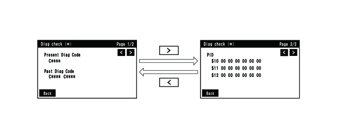
| Indication Name | Measurement Item | Note |
|---|---|---|
| Prsent Diag Code | Current DTC | DTCs output when the parking assist ECU detects a malfunction |
| Past Diag Code | Past DTC | |
| PID | PID table | Values based on information displayed on Data List |
(c) Finish diagnostic mode.
-
w/ Audio and Visual System:
Click here
-
w/ Navigation System:
Click here
SIGNAL CHECK (parking assist ECU input signal)
(a) Start diagnostic mode.
-
w/ Audio and Visual System:
Click here
-
w/ Navigation System:
Click here
(1) Select "Function Check/Setting" on the "Service Menu" screen to display the "Function Check/Setting I" screen.
(2) Select "Camera Setting" on the "Function Check/Setting I" screen.
NOTICE:
If the "Camera Setting" selection screen is not displayed, turn the power switch off and enter the diagnosis screen after turning the power switch on (IG) once again.
HINT:
After "Camera Setting" is selected, the screen transitions differ depending on whether initialization of the parking assist ECU was performed after parking assist ECU replacement.
| Parking Assist ECU Initialization | Screen Transition |
|---|---|
| Not performed | "Signal Check" screen |
| Performed | "Mode Setting" screen |
(3) When the screen changes to the "Mode Setting" screen, select "View Adjustment" to display the "Signal Check" screen.
HINT:
To select a grayed out item, select and hold the item for 2 seconds or more.
(b) Signal check
(1) On the "Signal Check" screen, it is possible to inspect the state of signals sent to the parking assist ECU and check the settings.
| Item | Inspection Detail | Note |
|---|---|---|
| CAN | Speed signal input | When "CHK" (red) is displayed, selecting "Next" will not change to the next screen. |
| CAMERA SW | No. 2 combination switch assembly (panoramic view monitor main switch) signal input | |
| SHIFT | Reverse signal input |
HINT:
- When "CHK" (red) is displayed, perform inspections based on the result of the following inspections.
- If performing the adjustment after proceeding to the next screen, confirm that all items display "OK" (blue) before selecting "Next".
.png)
(c) CAN inspection
HINT:
If "CHK" (red) is displayed for "CAN", check for DTCs and perform troubleshooting based on the output DTCs.
Click here
(d) CAMERA SW inspection
(1) Check that "OK" (blue) is displayed for "CAMERA SW" and select "OK".
HINT:
If "CHK" (red) remains displayed or the "CAMERA SW" inspection result is not normal, perform troubleshooting according to the Problem Symptoms Table ("CHK" message(s) are displayed on the "Signal Check" screen).
Click here
(e) SHIFT inspection
(1) Check that "OK" (blue) is displayed for "SHIFT" and select "OK".
HINT:
If "CHK" (red) remains displayed or the "SHIFT" inspection result is not normal, perform troubleshooting according to the Problem Symptoms Table ("CHK" message(s) are displayed on the "Signal Check" screen).
Click here
(f) Finish diagnostic mode.
-
w/ Audio and Visual System:
Click here
-
w/ Navigation System:
Click here
HINT:
- Use this function when symptoms such as the camera images not being displayed occur.
- On the DTC screen, the 4 camera images are displayed as one image and the images input to the parking assist ECU from the cameras can be checked.
CAMERA CHECK
(a) Start diagnostic mode.
-
w/ Audio and Visual System:
Click here
-
w/ Navigation System:
Click here
(1) Select "Function Check/Setting" on the "Service Menu" screen to display the "Function Check/Setting I" screen.
(2) Select "Camera Setting" on the "Function Check/Setting I" screen.
NOTICE:
If the "Camera Setting" selection screen is not displayed, turn the power switch off and enter the diagnosis screen after turning the power switch on (IG) once again.
HINT:
After "Camera Setting" is selected, the screen transitions differ depending on whether initialization of the parking assist ECU was performed after parking assist ECU replacement.
| Parking Assist ECU Initialization | Screen Transition |
|---|---|
| Not performed | "Signal Check" screen |
| Performed | "Mode Setting" screen |
(3) When the screen changes to the "Mode Setting" screen, select "View Adjustment" to display the "Signal Check" screen.
HINT:
To select a grayed out item, select and hold the item for 2 seconds or more.
(b) Check camera images
(1) On the "Camera Check" screen, the images that are input to the parking assist ECU from the 4 cameras are displayed on the screen and the camera images can be checked.
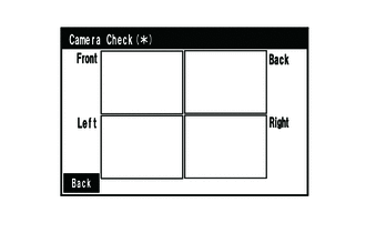
| Indication Name | Measurement Item | Indication Name | Measurement Item |
|---|---|---|---|
| Front | Front television camera assembly | Back | Rear television camera assembly |
| Left | Side television camera assembly LH | Right | Side television camera assembly RH |
(c) Finish diagnostic mode.
-
w/ Audio and Visual System:
Click here
-
w/ Navigation System:
Click here
CALIBRATION WHEN SERVICING VEHICLE
NOTICE:
Depending on the parts that are replaced or operations that are performed during vehicle inspection or maintenance, calibration of other systems as well as the panoramic view monitor system may be needed.
Click here
READ NEXT:
 Dtc Check / Clear
DTC CHECK / CLEAR CHECK DTC (a) Connect the Techstream to the DLC3. (b) Turn the power switch on (IG). (c) Turn the Techstream on. (d) Enter the following menus: Chassis / Panoramic View Monitor / Tro
Data List / Active Test
DATA LIST / ACTIVE TEST DATA LIST HINT: Using the Techstream to read the Data List allows the values or states of switches, sensors, actuators and other items to be read without removing any parts. Th
Diagnostic Trouble Code Chart
DIAGNOSTIC TROUBLE CODE CHART Panoramic View Monitor System DTC No. Detection Item Link C1614 ECU Malfunction C1621 Back Camera Power Supply Failure C1622 Open or Sh
SEE MORE:
Battery Thermometer Sensor
On-vehicle InspectionON-VEHICLE INSPECTION PROCEDURE 1. INSPECT THERMISTOR ASSEMBLY (a) Disconnect the thermistor assembly connector. *a Component without harness connected (Thermistor Assembly) *b Sensing Portion *c Resistance *d Temperature *e Allowable R
Components
COMPONENTS ILLUSTRATION *1 COWL SIDE TRIM BOARD LH *2 DOOR SCUFF PLATE ASSEMBLY LH *3 FRONT FLOOR CARPET ASSEMBLY *4 NO. 4 DASH PANEL INSULATOR PAD (FRONT FLOOR FOOTREST)
