Lexus NX: Disassembly
DISASSEMBLY
PROCEDURE
1. REMOVE ENGINE COVER JOINT
| (a) Remove the 3 engine cover joints. |
|
2. REMOVE SPARK PLUG
Click here .gif)
3. REMOVE KNOCK CONTROL SENSOR
Click here
4. REMOVE ENGINE COOLANT TEMPERATURE SENSOR
Click here
5. REMOVE ENGINE OIL PRESSURE SWITCH ASSEMBLY
Click here
6. REMOVE CAMSHAFT TIMING OIL CONTROL VALVE ASSEMBLY
Click here
7. REMOVE CAMSHAFT POSITION SENSOR
Click here
8. REMOVE OIL FILLER CAP SUB-ASSEMBLY
(a) Remove the oil filler cap sub-assembly from the cylinder head cover sub-assembly.
(b) Remove the oil filler cap gasket from the oil filler cap sub-assembly.
9. REMOVE CRANKSHAFT POSITION SENSOR
Click here
10. REMOVE PCV VALVE
Click here
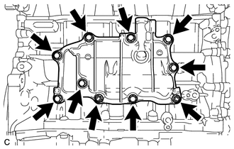
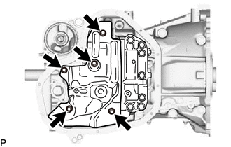
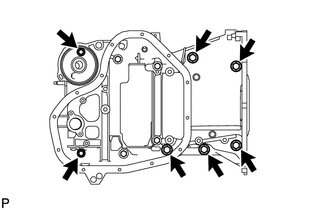
11. REMOVE PCV CASE
| (a) Remove the 8 bolts and 2 nuts. |
|
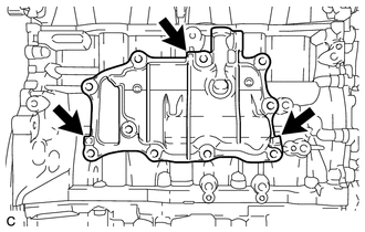
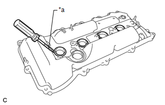
| (b) Remove the PCV case by prying between the PCV case and cylinder block with a screwdriver. NOTICE: Be careful not to damage the contact surfaces of the cylinder block and PCV case. HINT: Tape the screwdriver tip before use. |
|
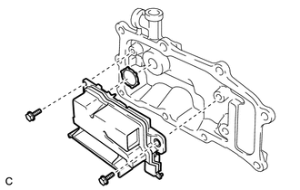
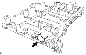
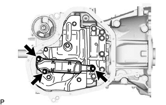
12. REMOVE SEPARATOR CASE
| (a) Remove the 2 bolts, separator case and gasket. |
|
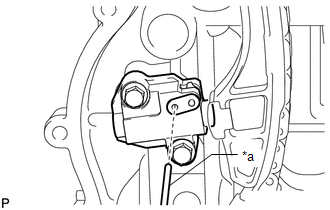
13. REMOVE CRANKSHAFT PULLEY ASSEMBLY
(a) Using SST, hold the crankshaft pulley assembly and loosen the crankshaft pulley set bolt until 2 or 3 threads are screwed into the crankshaft.
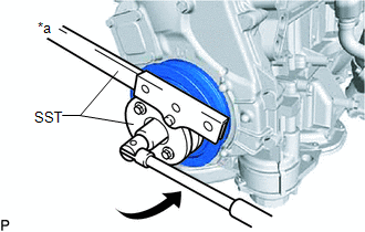
| *a | Hold |
.png) | Turn |
SST: 09213-54015
SST: 09330-00021
HINT:
Part number of installation bolt for SST (crankshaft pulley holding tool): 91551-80650 (quantity: 2)
(b) Using SST, remove the crankshaft pulley assembly and crankshaft pulley set bolt.
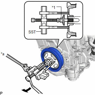
| *1 | Crankshaft Pulley Set Bolt |
| *a | Hold |
| | Turn |
SST: 09950-50013
09951-05010
09952-05010
09953-05020
09954-05011
09957-04010
HINT:
Apply lubricant to the threads and end of SST.
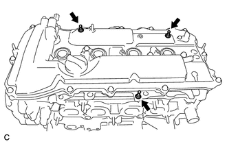
14. REMOVE CYLINDER HEAD COVER SUB-ASSEMBLY
| (a) Remove the 16 bolts, 3 seal washers, cylinder head cover sub-assembly and cylinder head cover gasket from the camshaft housing sub-assembly. |
|
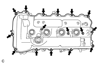
| (b) Remove the 2 gaskets from the camshaft bearing caps. |
|
15. REMOVE SPARK PLUG TUBE GASKET
| (a) Remove the 4 spark plug tube gaskets with a screwdriver. NOTICE: Be careful not to damage the cylinder head cover sub-assembly. HINT: Tape the screwdriver tip before use. |
|
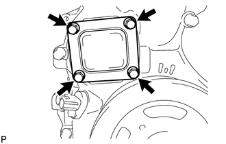
16. REMOVE ENGINE MOUNTING BRACKET RH
(a) Remove the 4 bolts and engine mounting bracket RH.
17. REMOVE ENGINE MOUNTING BRACKET RH STUD BOLT
NOTICE:
If a stud bolt is deformed or its threads are damaged, replace it.
18. REMOVE TIMING CHAIN COVER ASSEMBLY
Click here
19. REMOVE TIMING CHAIN COVER OIL SEAL
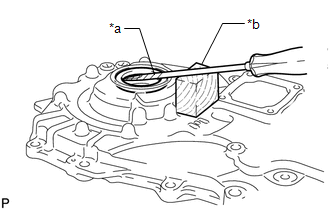
| (a) Using a screwdriver and wooden block, pry out the timing chain cover oil seal. NOTICE: Do not damage the surface of the timing chain cover oil seal press fit hole. HINT: Tape the screwdriver tip before use. |
|
20. REMOVE TIMING CHAIN COVER TIGHT PLUG
| (a) Using a 14 mm hexagon wrench, remove the timing chain cover tight plug and gasket. |
|
21. REMOVE TIMING CHAIN COVER PLATE
| (a) Remove the 4 bolts, timing chain cover plate and gasket. |
|
22. SET NO. 1 CYLINDER TO TDC/COMPRESSION
(a) Temporarily install the crankshaft pulley set bolt.
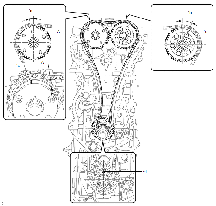
| *1 | Crankshaft Pulley Set Key | - | - |
| *a | Approximately 7° | *b | Approximately 32° |
| *c | Timing Mark | - | - |
HINT:
"A" in the illustration is not a timing mark.
(b) Rotate the crankshaft clockwise so that the timing marks on the crankshaft timing sprocket, camshaft timing gear assembly and camshaft timing sprocket are as shown in the illustration.
HINT:
If the timing marks do not align, rotate the crankshaft clockwise again and align the timing marks.
(c) Remove the crankshaft pulley set bolt.
23. REMOVE TIMING CHAIN GUIDE
| (a) Remove the bolt and timing chain guide. |
|
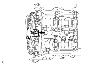
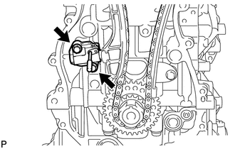
24. REMOVE NO. 1 CHAIN TENSIONER ASSEMBLY
| (a) Allow the plunger to extend slightly, and then rotate the stopper plate counterclockwise to release the lock. Once the lock is released, push the plunger into the No. 1 chain tensioner assembly. |
|
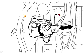
| (b) Move the stopper plate clockwise to set the lock, and then insert a pin into the stopper plate hole. |
|
| (c) Remove the 2 bolts, No. 1 chain tensioner assembly and gasket. |
|
25. REMOVE CHAIN TENSIONER SLIPPER
| (a) Remove the bolt and chain tensioner slipper. |
|
26. REMOVE CHAIN SUB-ASSEMBLY
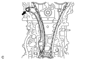
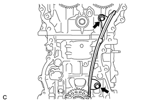
27. REMOVE NO. 1 CHAIN VIBRATION DAMPER
| (a) Remove the 2 bolts and No. 1 chain vibration damper. |
|
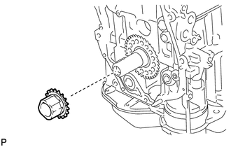
28. REMOVE CRANKSHAFT TIMING SPROCKET
| (a) Remove the crankshaft timing sprocket from the crankshaft. |
|
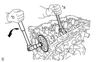
29. REMOVE CAMSHAFT TIMING GEAR ASSEMBLY
| (a) Hold the hexagonal portion of the camshaft with a wrench and remove the bolt and camshaft timing gear assembly. NOTICE:
|
|
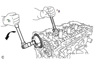
30. REMOVE CAMSHAFT TIMING SPROCKET
| (a) Hold the hexagonal portion of the No. 2 camshaft with a wrench and remove the bolt and camshaft timing sprocket. NOTICE: Be careful not to damage the camshaft housing sub-assembly or spark plug tube with the wrench. |
|
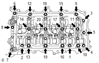
31. REMOVE CAMSHAFT HOUSING SUB-ASSEMBLY
| (a) Uniformly loosen and remove the 20 bearing cap bolts in the sequence shown in the illustration. |
|
| (b) Remove the camshaft housing sub-assembly by prying between the cylinder head sub-assembly and camshaft housing sub-assembly with a screwdriver. NOTICE: Be careful not to damage the contact surfaces of the cylinder head sub-assembly and camshaft housing sub-assembly. HINT: Tape the screwdriver tip before use. |
|
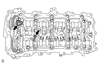
32. REMOVE CAMSHAFT BEARING CAP
| (a) Remove the 11 bearing cap bolts in the sequence shown in the illustration. |
|
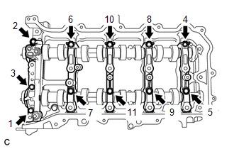
(b) Remove the 5 camshaft bearing caps.
HINT:
Arrange the removed parts in the correct order.
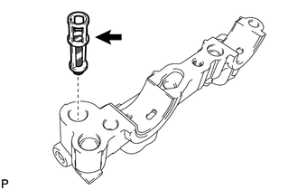
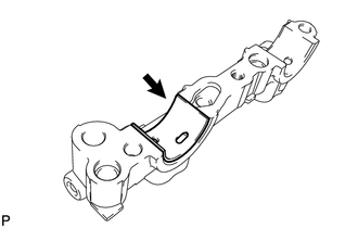
33. REMOVE OIL CONTROL VALVE FILTER
| (a) Remove the oil control valve filter from the No. 1 camshaft bearing cap. |
|
34. REMOVE CAMSHAFT
(a) Remove the camshaft from the camshaft housing sub-assembly.
35. REMOVE NO. 2 CAMSHAFT
(a) Remove the No. 2 camshaft from the camshaft housing sub-assembly.
36. REMOVE NO. 1 CAMSHAFT BEARING
| (a) Remove the No. 1 camshaft bearing. |
|
37. REMOVE NO. 2 CAMSHAFT BEARING
| (a) Remove the No. 2 camshaft bearing. |
|
38. REMOVE CAMSHAFT BEARING CAP SETTING RING PIN
NOTICE:
It is not necessary to remove the ring pin unless it is being replaced.
39. REMOVE CAMSHAFT HOUSING STUD BOLT
NOTICE:
If a stud bolt is deformed or its threads are damaged, replace it.
40. REMOVE CAMSHAFT HOUSING STRAIGHT PIN
NOTICE:
It is not necessary to remove the straight pin unless it is being replaced.
41. REMOVE NO. 1 VALVE ROCKER ARM SUB-ASSEMBLY
(a) Remove the 16 No. 1 valve rocker arm sub-assemblies from the cylinder head sub-assembly.
HINT:
Arrange the removed parts in the correct order.
42. REMOVE VALVE LASH ADJUSTER ASSEMBLY
(a) Remove the 16 valve lash adjuster assemblies from the cylinder head sub-assembly.
HINT:
Arrange the removed parts in the correct order.
43. REMOVE VALVE STEM CAP
(a) Remove the 16 valve stem caps from the cylinder head sub-assembly.
HINT:
Arrange the removed parts in the correct order.
44. REMOVE CYLINDER HEAD SUB-ASSEMBLY
Click here
45. REMOVE CYLINDER HEAD GASKET
Click here
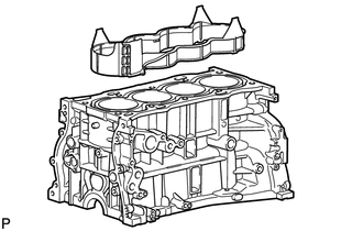
46. REMOVE CYLINDER BLOCK WATER JACKET SPACER
| (a) Remove the cylinder block water jacket spacer from the cylinder block. NOTICE: Be sure to remove the water jacket spacer. If it is not removed, it may fall and become damaged when the cylinder block is inverted. |
|
47. REMOVE OIL FILTER ELEMENT
Click here
48. REMOVE OIL PAN SUB-ASSEMBLY
| (a) Remove the 11 bolts and 2 nuts. |
|
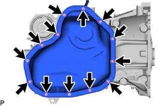
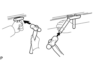
| (b) Insert the blade of an oil pan seal cutter between the oil pan sub-assembly and stiffening crankcase assembly, cut off the applied sealer and remove the oil pan sub-assembly. NOTICE:
|
|
49. REMOVE OIL STRAINER SUB-ASSEMBLY
| (a) Remove the 3 bolts, oil strainer sub-assembly and gasket. |
|
50. REMOVE NO. 1 OIL PAN BAFFLE PLATE
| (a) Remove the 5 bolts and No. 1 oil pan baffle plate. |
|
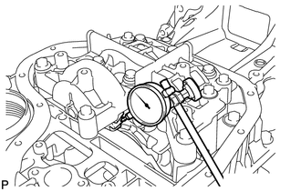
51. INSPECT CRANKSHAFT BACKLASH
| (a) Using a dial indicator, measure the backlash of the crankshaft and balance shaft as shown in the illustration. Standard backlash: 0.05 to 0.20 mm (0.00197 to 0.00787 in.) Maximum backlash: 0.20 mm (0.00787 in.) If the backlash is more than the maximum, replace the engine balancer assembly. |
|
52. REMOVE ENGINE BALANCER ASSEMBLY
| (a) Remove the 7 bolts and engine balancer assembly. NOTICE: Do not disassemble the engine balancer assembly. |
|
53. INSPECT BALANCE SHAFT THRUST CLEARANCE
Click here
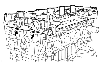
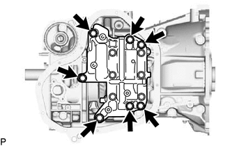
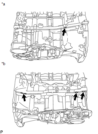
54. REMOVE STIFFENING CRANKCASE ASSEMBLY
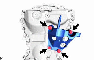
| (a) Remove the 7 bolts. |
|
| (b) Using a screwdriver, remove the stiffening crankcase assembly by prying between the stiffening crankcase assembly and cylinder block at the places shown in the illustration. NOTICE: Be careful not to damage the contact surfaces of the cylinder block and stiffening crankcase assembly. HINT: Tape the screwdriver tip before use. |
|
55. REMOVE CYLINDER BLOCK STUD BOLT
NOTICE:
If a stud bolt is deformed or its threads are damaged, replace it.
56. REMOVE STIFFENING CRANKCASE STUD BOLT
NOTICE:
If a stud bolt is deformed or its threads are damaged, replace it.
57. REMOVE STIFFENING CRANKCASE RING PIN
NOTICE:
It is not necessary to remove the ring pin unless it is being replaced.
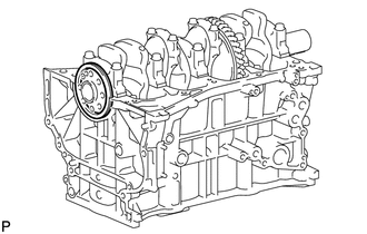
58. REMOVE REAR ENGINE OIL SEAL
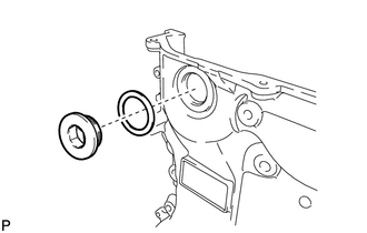
| (a) Remove the rear engine oil seal from the cylinder block. |
|
READ NEXT:
 Inspection
INSPECTION PROCEDURE 1. INSPECT NO. 1 VALVE ROCKER ARM SUB-ASSEMBLY (a) Turn the roller by hand and check that it turns smoothly. If the roller does not turn smoothly, replace the No. 1 valve rocker a
Reassembly
REASSEMBLY PROCEDURE 1. INSTALL STIFFENING CRANKCASE RING PIN NOTICE: It is not necessary to remove the ring pin unless it is being replaced. *a Protrusion Height (a) Using a plastic-faced ha
Installation
INSTALLATION PROCEDURE 1. INSTALL IGNITION COIL ASSEMBLY Click here 2. INSTALL SENSOR WIRE (a) Install the sensor wire with the bolt. Torque: 21 N·m {214 kgf·cm, 15 ft·lbf} (b) Connect the knock
SEE MORE:
Engine Immobiliser System Malfunction (B2799-790)
DESCRIPTION When there is a communication malfunction between the hybrid vehicle control ECU and ID code box (immobiliser code ECU), or when the communication ID codes do not match, the hybrid vehicle control ECU stores this DTC. DTC No. Detection Item DTC Detection Condition Trouble Area
Short in Curtain Shield Airbag (LH) Squib Circuit (B1835-B1838)
DESCRIPTION The curtain shield squib LH circuit consists of the airbag ECU assembly and curtain shield airbag assembly LH. The circuit instructs the SRS to deploy when deployment conditions are met. These DTCs are stored when a malfunction is detected in the curtain shield squib LH circuit. DTC N
