Lexus NX: Reassembly
REASSEMBLY
PROCEDURE
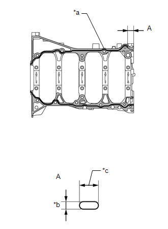
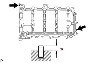
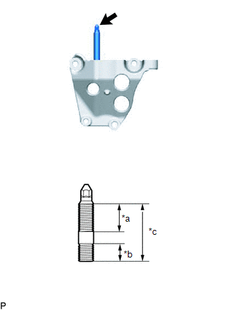
1. INSTALL STIFFENING CRANKCASE RING PIN
NOTICE:
It is not necessary to remove the ring pin unless it is being replaced.
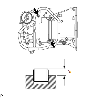
| *a | Protrusion Height |
(a) Using a plastic-faced hammer, tap in 2 new ring pins until they stop.
Standard protrusion height:
4.3 to 5.3 mm (0.169 to 0.209 in.)
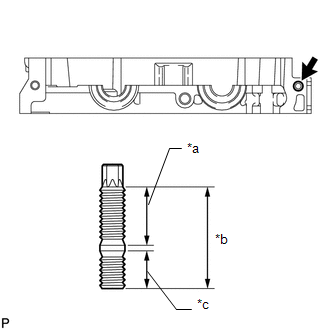
2. INSTALL STIFFENING CRANKCASE STUD BOLT
NOTICE:
If a stud bolt is deformed or its threads are damaged, replace it.
(a) Using an E5 and E8 "TORX" socket wrench, install the stud bolts.
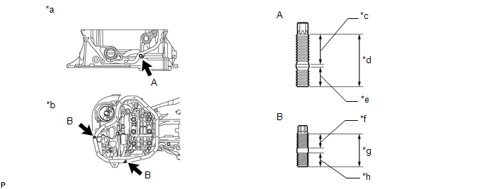
| *a | Front Side | *b | Lower Side |
| *c | 20 mm (0.787 in.) | *d | 35 mm (1.38 in.) |
| *e | 13 mm (0.512 in.) | *f | 8.5 mm (0.335 in.) |
| *g | 18 mm (0.709 in.) | *h | 8.0 mm (0.315 in.) |
Torque:
for stud bolt A :
9.5 N·m {97 kgf·cm, 84 in·lbf}
for stud bolt B :
4.0 N·m {41 kgf·cm, 35 in·lbf}
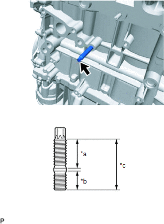
3. INSTALL CYLINDER BLOCK STUD BOLT
| (a) Using an E10 "TORX" socket wrench, install the stud bolts. Torque: 15 N·m {153 kgf·cm, 11 ft·lbf} |
|
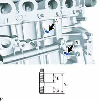
| (b) Using an E8 "TORX" socket wrench, install the stud bolt. Torque: 9.5 N·m {97 kgf·cm, 84 in·lbf} HINT: The stud bolt may be installed at either A or B. |
|
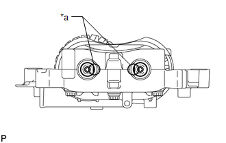
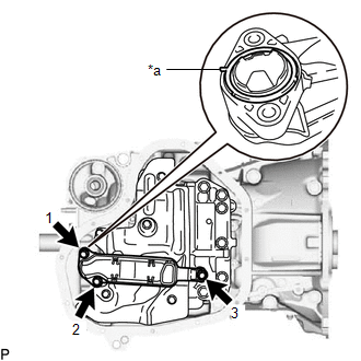
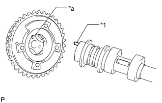
4. INSTALL ENGINE BALANCER ASSEMBLY
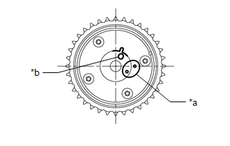
(a) Check that the alignment marks of the balance shaft damper cover and balance shaft driven gear are aligned.
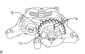
| *1 | Balance Shaft Damper Cover |
| *2 | Balance Shaft Driven Gear |
| *a | Alignment Mark |
If the alignment marks are not aligned, realign them.
| (1) Place a wrench on the rear cutout part of the No. 2 balance shaft and fix the shaft in place. |
|
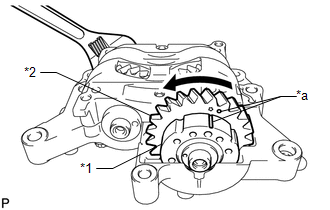
(2) Rotate the balance shaft driven gear of the No. 1 balance shaft counterclockwise to align the alignment mark of the balance shaft driven gear with the alignment mark of the balance shaft damper cover.
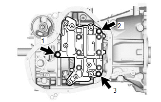
| (b) Install the engine balancer assembly to the stiffening crankcase with the 3 bolts and tighten the bolts in the sequence shown in the illustration. Torque: 24 N·m {245 kgf·cm, 18 ft·lbf} |
|
5. INSTALL STIFFENING CRANKCASE ASSEMBLY
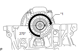
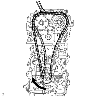
| (a) Rotate the crankshaft clockwise so that the crankshaft pulley set key is at the position 270° from the bottom as shown in the illustration. |
|
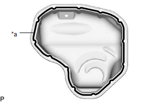
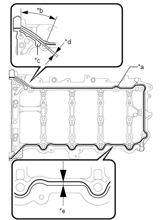
(b) Apply seal packing to the areas as shown in the illustration.
| *a | Seal Packing |
| *b | 2.5 to 3.5 mm (0.0984 to 0.138 in.) |
| *c | 7.0 to 9.0 mm (0.276 to 0.354 in.) |
.png) | Stiffening Crankcase |
.png) | Cylinder Block |
Seal packing:
Toyota Genuine Seal Packing Black, Three Bond 1207B or equivalent
Standard Seal Dimension:
| Area | Specified Condition |
|---|---|
| Continuous Line | 2.5 to 3.5 mm (0.0984 to 0.138 in.) |
| Dashed Line | 7.0 to 9.0 mm (0.276 to 0.354 in.) wide and 2.5 to 3.5 mm (0.0984 to 0.138 in.) thick |
Application length A:
28 mm (1.10 in.)
NOTICE:
- Remove any oil from the contact surface.
- Install the stiffening crankcase assembly within 3 minutes and tighten the bolts and nuts within 15 minutes after applying seal packing.
- Do not apply oil for at least 4 hours after the installation.
- Do not start the engine for at least 4 hours after the installation.
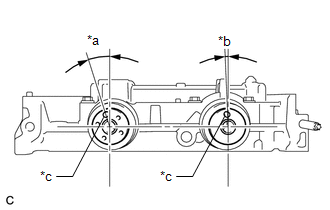
| (c) Check that the rear cutouts are as shown in the illustration. |
|
(d) Clean the bolts and their installation holes.
(e) Apply adhesive to 3 threads or more at the end of bolt A.
Adhesive:
Toyota Genuine Adhesive 1344, Three Bond 1344 or equivalent
| (f) Temporarily install the stiffening crankcase assembly with the 11 bolts. Bolt Length :
HINT: Apply adhesive to bolt A before installing it. |
|
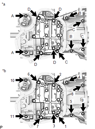
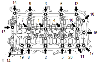
(g) Tighten the 11 bolts in the sequence shown in the illustration to install the stiffening crankcase assembly.
Torque:
for bolt A :
24 N·m {245 kgf·cm, 18 ft·lbf}
except bolt A :
43 N·m {438 kgf·cm, 32 ft·lbf}
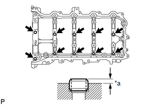
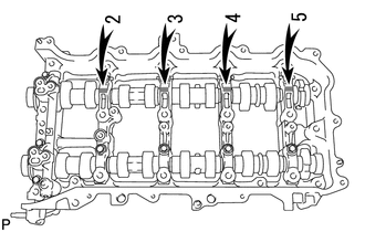
6. INSTALL NO. 1 OIL PAN BAFFLE PLATE
| (a) Install the No. 1 oil pan baffle plate and uniformly tighten the 5 bolts in several steps in the sequence shown in the illustration. Torque: 10 N·m {102 kgf·cm, 7 ft·lbf} |
|
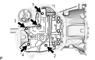
7. INSTALL OIL STRAINER SUB-ASSEMBLY
| (a) Apply a light coat of engine oil to a new gasket. |
|
(b) Align the protrusion of the gasket with the cutout of the oil strainer sub-assembly and install the gasket to the oil strainer sub-assembly.
(c) Install the oil strainer sub-assembly with the 3 bolts in several steps in the sequence shown in the illustration.
Torque:
9.0 N·m {92 kgf·cm, 80 in·lbf}
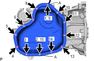
8. INSTALL OIL PAN SUB-ASSEMBLY
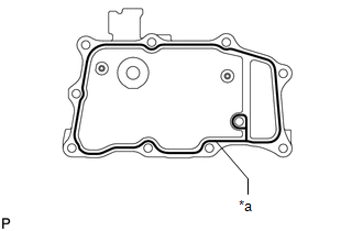
| (a) Apply seal packing in a continuous line as shown in the illustration. Seal packing: Toyota Genuine Seal Packing Black, Three Bond 1207B or equivalent Standard seal diameter: 2.5 to 3.5 mm (0.0984 to 0.138 in.) NOTICE:
|
|
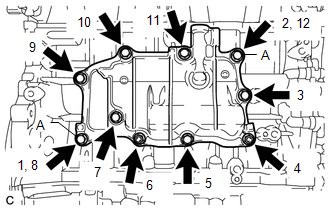
| (b) Install the oil pan sub-assembly with the 11 bolts and 2 nuts in several steps in the sequence shown in the illustration. Torque: 10 N·m {102 kgf·cm, 7 ft·lbf} HINT: Bolt A and nut A are tightened twice. |
|
9. INSTALL OIL FILTER ELEMENT
Click here .gif)
10. INSTALL REAR ENGINE OIL SEAL
Click here
11. INSTALL CYLINDER BLOCK WATER JACKET SPACER
(a) Install the cylinder block water jacket spacer to the cylinder block.
12. INSTALL CYLINDER HEAD GASKET
Click here
13. INSTALL CYLINDER HEAD SUB-ASSEMBLY
Click here
14. INSTALL CAMSHAFT BEARING CAP SETTING RING PIN
NOTICE:
It is not necessary to remove the ring pin unless it is being replaced.
| *a | Protrusion Height |
(a) Using a plastic-faced hammer, tap in 10 new ring pins to the camshaft housing sub-assembly.
Standard protrusion height:
2.7 to 3.3 mm (0.106 to 0.130 in.)
15. INSTALL CAMSHAFT HOUSING STRAIGHT PIN
NOTICE:
It is not necessary to remove the straight pin unless it is being replaced.
| *a | Protrusion Height |
(a) Using a plastic-faced hammer, tap in 2 new straight pins to the camshaft housing sub-assembly.
Standard protrusion height:
5.0 to 7.0 mm (0.197 to 0.276 in.)
16. INSTALL CAMSHAFT HOUSING STUD BOLT
NOTICE:
If a stud bolt is deformed or its threads are damaged, replace it.
(a) Apply adhesive to the camshaft housing side threads of the stud bolt.
Adhesive:
Toyota Genuine Adhesive 1324, Three Bond 1324 or equivalent.
| (b) Using an E8 "TORX" socket wrench, install the stud bolt. Torque: 9.0 N·m {92 kgf·cm, 80 in·lbf} |
|
17. INSTALL NO. 1 CAMSHAFT BEARING
| (a) Clean the No. 1 camshaft bearing. |
|
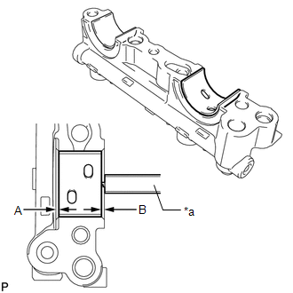
(b) Install the camshaft bearing to the No. 1 camshaft bearing cap.
(c) Using a vernier caliper, measure the distance between the camshaft bearing cap edge and the camshaft bearing edge.
Dimension A - B or B - A:
0 to 0.7 mm (0 to 0.0276 in.)
18. INSTALL NO. 2 CAMSHAFT BEARING
| (a) Clean the No. 2 camshaft bearing. |
|
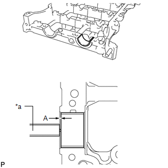
(b) Install the camshaft bearing to the camshaft housing sub-assembly.
(c) Using a vernier caliper, measure the distance between the camshaft housing edge and the camshaft bearing edge.
Standard distance:
1.15 to 1.85 mm (0.0453 to 0.0728 in.)
19. INSTALL OIL CONTROL VALVE FILTER
(a) Install the oil control valve filter to the No. 1 camshaft bearing cap.
20. INSTALL NO. 2 CAMSHAFT
(a) Clean the camshaft journals, camshaft housing sub-assembly and camshaft bearing caps.
(b) Apply a light coat of engine oil to the camshaft journal, camshaft housing sub-assembly and camshaft bearing caps.
(c) Install the No. 2 camshaft to the camshaft housing sub-assembly.
21. INSPECT CAMSHAFT TIMING GEAR ASSEMBLY
Click here
22. INSTALL CAMSHAFT
(a) Clean the camshaft journals, camshaft housing sub-assembly and camshaft bearing caps.
(b) Apply a light coat of engine oil to the camshaft journal, camshaft housing sub-assembly and camshaft bearing caps.
(c) Install the camshaft to the camshaft housing sub-assembly.
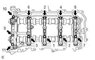
23. INSTALL CAMSHAFT BEARING CAP
| (a) Confirm the marks and numbers on the camshaft bearing caps and place them in their proper positions and directions. |
|
| (b) Install the 11 bearing cap bolts in the order shown in the illustration. Torque: 16 N·m {163 kgf·cm, 12 ft·lbf} NOTICE: Make sure that the camshaft rotates smoothly after installing the bearing caps. |
|
24. INSTALL VALVE STEM CAP
(a) Apply a light coat of engine oil to the valve stem ends.
(b) Install the 16 valve stem caps to the cylinder head sub-assembly.
NOTICE:
Do not drop the valve stem caps into the cylinder head sub-assembly.
25. INSTALL VALVE LASH ADJUSTER ASSEMBLY
(a) Inspect the valve lash adjuster before installing it.
Click here
(b) Install the 16 valve lash adjuster assemblies to the cylinder head sub-assembly.
NOTICE:
Install the valve lash adjuster to the same place it was removed from.
26. INSTALL NO. 1 VALVE ROCKER ARM SUB-ASSEMBLY
| (a) Apply engine oil to the valve lash adjuster tips and valve stem caps. |
|
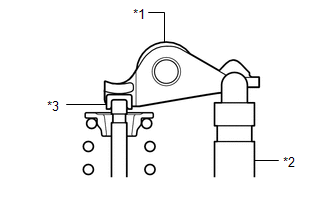
(b) Install the 16 No. 1 valve rocker arm sub-assemblies as shown in the illustration.
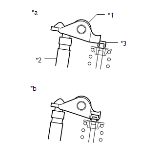
27. INSTALL CAMSHAFT HOUSING SUB-ASSEMBLY
| (a) Check that the No. 1 valve rocker arm sub-assemblies are installed as shown in the illustration. |
|
| (b) Apply seal packing to the areas as shown in the illustration. Seal packing: Toyota Genuine Seal Packing Black, Three Bond 1207B or equivalent Apply Seal Packing as Follows:
NOTICE:
|
|
| (c) Position the knock pin of the camshaft and No. 2 camshaft as shown in the illustration. |
|
| (d) Install the camshaft housing sub-assembly, and then install the 20 bearing cap bolts in the order shown in the illustration. Torque: 27 N·m {275 kgf·cm, 20 ft·lbf} NOTICE:
|
|
28. INSTALL CAMSHAFT TIMING GEAR ASSEMBLY
| (a) Check the camshaft timing gear position. If the camshaft timing gear assembly is not set the advanced position, release the lock pin and reset the camshaft timing gear assembly (refer to Set Camshaft Timing Gear Assembly procedures). |
|
| (b) Align the knock pin of the camshaft with the knock pin hole of the camshaft timing gear assembly and attach the camshaft timing gear assembly to the camshaft. |
|
| (c) Check that there is no clearance between the camshaft timing gear assembly and camshaft flange. |
|
.png)
(d) Using a wrench to hold the hexagonal portion of the camshaft, install the bolt.
| *a | Hold |
.png) | Turn |
Torque:
85 N·m {867 kgf·cm, 63 ft·lbf}
NOTICE:
- Be careful not to damage the camshaft housing sub-assembly or spark plug tube with the wrench.
- Do not disassemble the camshaft timing gear assembly.
29. INSTALL CAMSHAFT TIMING SPROCKET
(a) Using a wrench to hold the hexagonal portion of the No. 2 camshaft, install the camshaft timing sprocket with the bolt.
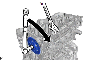
| *a | Hold |
| | Turn |
Torque:
85 N·m {867 kgf·cm, 63 ft·lbf}
NOTICE:
Be careful not to damage the camshaft housing sub-assembly or spark plug tube with the wrench.
30. INSTALL CRANKSHAFT TIMING SPROCKET
(a) Install the crankshaft timing sprocket to the crankshaft.
31. ADD ENGINE OIL
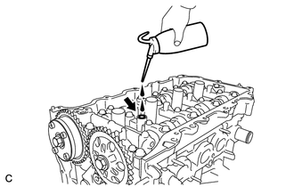
| (a) Add 50 cc (3.1 cu.in.) of engine oil into the oil hole shown in the illustration. NOTICE:
|
|
32. SET NO. 1 CYLINDER TO TDC/COMPRESSION
| (a) Temporarily install the crankshaft pulley set bolt. |
|
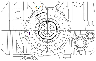
(b) Rotate the crankshaft 40° counterclockwise to position the crankshaft pulley set key as shown in the illustration.
| (c) Check that the timing marks of the camshaft timing gear assembly and camshaft timing sprocket are as shown in the illustration. HINT: "A" in the illustration is not a timing mark. |
|
(d) Remove the crankshaft pulley set bolt.
33. INSTALL NO. 1 CHAIN VIBRATION DAMPER
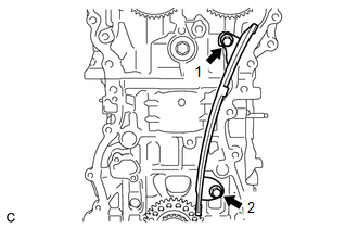
| (a) Install the No. 1 chain vibration damper with the 2 bolts in the order shown in the illustration. Torque: 21 N·m {214 kgf·cm, 15 ft·lbf} |
|
34. INSTALL CHAIN SUB-ASSEMBLY
HINT:
Confirm the color of each mark plate before installing the chain sub-assembly.
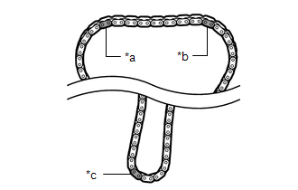
| *a | for Intake Side |
| *b | for Exhaust Side |
| *c | for Crankshaft |
| Type of Chain Sub-assembly | for Exhaust Side | for Intake Side | for Crankshaft |
|---|---|---|---|
| Type A | Gold | Gold | Gold |
| Type B | Orange | Orange | Yellow |
(a) Place the chain sub-assembly onto the camshaft timing gear assembly, camshaft timing sprocket and crankshaft timing sprocket.
HINT:
- Make sure the mark plate of the chain sub-assembly faces away from the engine.
- It is not necessary to install the chain sub-assembly to the teeth of the gear and sprockets.
| (b) Align the mark plate (for Exhaust Side) of the chain sub-assembly with the timing mark of the camshaft timing sprocket and install the chain sub-assembly to the camshaft timing sprocket. |
|
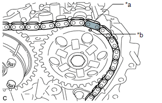
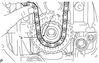
| (c) Align the mark plate (for Crankshaft) of the chain sub-assembly with the timing mark of the crankshaft timing sprocket and install the chain sub-assembly to the crankshaft timing sprocket. |
|
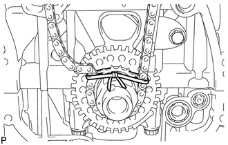
| (d) Tie a string above the crankshaft timing sprocket so that the chain sub-assembly is secure. |
|
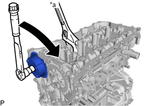
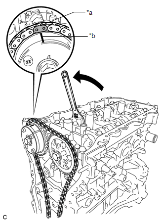
| (e) Using the hexagonal portion of the camshaft, rotate the camshaft counterclockwise with a wrench, align the timing mark of the camshaft timing gear assembly with the mark plate (for Intake Side) of the chain sub-assembly and install the chain sub-assembly to the camshaft timing gear assembly. HINT: Hold the camshaft in place with a wrench until the chain tensioner is installed. |
|
| (f) Remove the string above the crankshaft timing sprocket, rotate the crankshaft clockwise, and loosen the chain sub-assembly so that the chain tensioner slipper can be installed. NOTICE: Make sure the chain sub-assembly is secure. |
|
35. INSTALL CHAIN TENSIONER SLIPPER
(a) Install the chain tensioner slipper with the bolt.
Torque:
21 N·m {214 kgf·cm, 15 ft·lbf}
36. INSTALL NO. 1 CHAIN TENSIONER ASSEMBLY
(a) Install a new gasket and the No. 1 chain tensioner assembly with the 2 bolts.
Torque:
10 N·m {102 kgf·cm, 7 ft·lbf}
(b) Remove the pin from the stopper plate.
37. INSTALL TIMING CHAIN GUIDE
(a) Install the timing chain guide with the bolt.
Torque:
21 N·m {214 kgf·cm, 15 ft·lbf}
38. CHECK NO. 1 CYLINDER TO TDC/COMPRESSION
(a) Temporarily install the crankshaft pulley set bolt.
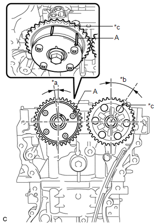
(b) Rotate the crankshaft clockwise, and check that the timing marks on the crankshaft timing sprocket, camshaft timing gear assembly and camshaft timing sprocket are as shown in the illustration.
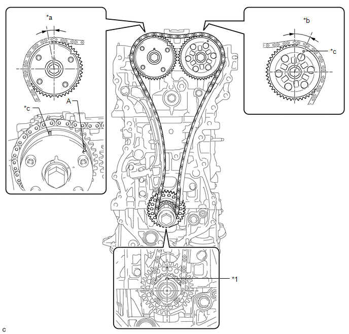
| *1 | Crankshaft Pulley Set Key | - | - |
| *a | Approximately 7° | *b | Approximately 32° |
| *c | Timing Mark | - | - |
HINT:
"A" in the illustration is not a timing mark.
(c) Remove the crankshaft pulley set bolt.
39. INSTALL TIMING CHAIN COVER PLATE
(a) Install a new gasket and the timing chain cover plate with the 4 bolts.
Torque:
10 N·m {102 kgf·cm, 7 ft·lbf}
40. INSTALL TIMING CHAIN COVER TIGHT PLUG
(a) Using a 14 mm hexagon wrench, install a new gasket and the timing chain cover tight plug.
Torque:
30 N·m {306 kgf·cm, 22 ft·lbf}
41. INSTALL TIMING CHAIN COVER ASSEMBLY
Click here
42. INSTALL ENGINE MOUNTING BRACKET RH STUD BOLT
NOTICE:
If a stud bolt is deformed or its threads are damaged, replace it.
| (a) Using an E8 "TORX" socket wrench, install the stud bolt. Torque: 15 N·m {153 kgf·cm, 11 ft·lbf} |
|
43. INSTALL ENGINE MOUNTING BRACKET RH
| (a) Temporarily install the engine mounting bracket RH with the 4 bolts. |
|
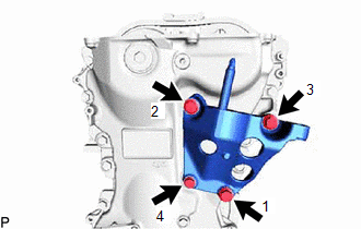
(b) Tighten the 4 bolts in the order shown in the illustration.
Torque:
for bolt 1, bolt 2 and bolt 3 :
55 N·m {561 kgf·cm, 41 ft·lbf}
for bolt 4 :
21 N·m {214 kgf·cm, 15 ft·lbf}
NOTICE:
After applying seal packing to the timing chain cover assembly, install the engine mounting bracket RH within 10 minutes.
44. INSTALL TIMING CHAIN COVER OIL SEAL
Click here
45. INSTALL SPARK PLUG TUBE GASKET
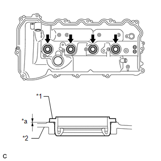
| (a) Install the 4 new spark plug tube gaskets to the cylinder head cover sub-assembly. NOTICE:
|
|
46. INSTALL CYLINDER HEAD COVER SUB-ASSEMBLY
(a) Apply a light coat of engine oil to 2 new gaskets.
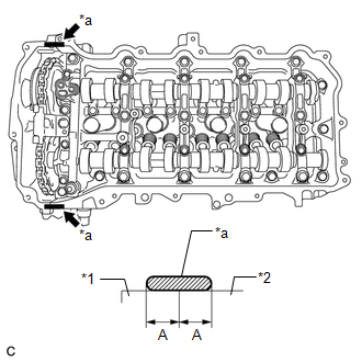
| (b) Install the gasket to the No. 2 camshaft bearing cap. |
|
.png)
(c) Install the gasket to the No. 1 camshaft bearing cap.
(d) Install a new cylinder head cover gasket to the cylinder head cover sub-assembly.
NOTICE:
Remove any oil from the contact surface.
| (e) Apply seal packing as shown in the illustration. Seal packing: Toyota Genuine Seal Packing Black, Three Bond 1207B or equivalent Standard seal diameter: 3.0 to 6.0 mm (0.118 to 0.236 in.) Application width A: 5.0 mm (0.197 in.) NOTICE:
|
|
| (f) Align the cylinder head cover sub-assembly with pin A. Then align the cylinder head cover sub-assembly with pin B and install the cylinder head cover sub-assembly. |
|
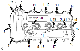
(g) Install the 3 new seal washers and 16 bolts, and then tighten the bolts in the order shown in the illustration.
Torque:
12 N·m {122 kgf·cm, 9 ft·lbf}
NOTICE:
- Do not add oil for at least 4 hours after the installation.
- Do not start the engine for at least 4 hours after the installation.
47. INSTALL CRANKSHAFT PULLEY ASSEMBLY
(a) Align the crankshaft pulley set key with the key groove of the crankshaft pulley assembly.
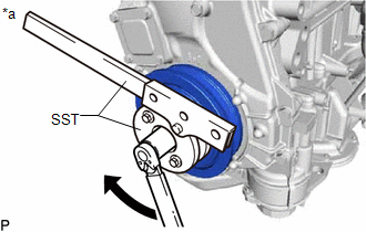
| *a | Hold |
| | Turn |
(b) Using SST, hold the crankshaft pulley assembly and install the crankshaft pulley set bolt.
SST: 09213-54015
SST: 09330-00021
Torque:
260 N·m {2651 kgf·cm, 192 ft·lbf}
HINT:
Part number of installation bolt for SST (crankshaft pulley holding tool): 91551-80650 (quantity: 2)
48. INSTALL SEPARATOR CASE
(a) Apply a light coat of engine oil to a new gasket.
(b) Install the gasket to the separator case.
(c) Install the separator case with the 2 bolts.
Torque:
10 N·m {102 kgf·cm, 7 ft·lbf}
49. INSTALL PCV CASE
| (a) Apply seal packing in a continuous line as shown in the illustration. Seal packing: Toyota Genuine Seal Packing Black, Three Bond 1207B or equivalent Standard seal diameter: 2.5 to 3.5 mm (0.0984 to 0.138 in.) NOTICE:
|
|
| (b) Install the PCV case, and then install the 8 bolts and 2 nuts in the order shown in the illustration. Torque: 21 N·m {214 kgf·cm, 15 ft·lbf} HINT: Bolt A is tightened twice. |
|
50. INSTALL PCV VALVE
Click here
51. INSTALL CRANKSHAFT POSITION SENSOR
Click here
52. INSTALL OIL FILLER CAP SUB-ASSEMBLY
(a) Install the oil filler cap gasket to the oil filler cap sub-assembly.
(b) Install the oil filler cap sub-assembly to the cylinder head cover sub-assembly.
53. INSTALL CAMSHAFT POSITION SENSOR
Click here
54. INSTALL CAMSHAFT TIMING OIL CONTROL VALVE ASSEMBLY
Click here
55. INSTALL ENGINE OIL PRESSURE SWITCH ASSEMBLY
Click here
56. INSTALL ENGINE COOLANT TEMPERATURE SENSOR
Click here
57. INSTALL KNOCK CONTROL SENSOR
Click here
58. INSTALL SPARK PLUG
Click here
59. INSTALL ENGINE COVER JOINT
(a) Install the 3 engine cover joints.
Torque:
10 N·m {102 kgf·cm, 7 ft·lbf}
READ NEXT:
 Installation
INSTALLATION PROCEDURE 1. INSTALL IGNITION COIL ASSEMBLY Click here 2. INSTALL SENSOR WIRE (a) Install the sensor wire with the bolt. Torque: 21 N·m {214 kgf·cm, 15 ft·lbf} (b) Connect the knock
Components
COMPONENTS ILLUSTRATION *1 FRONT SUSPENSION MEMBER REINFORCEMENT RH *2 NO. 1 ENGINE UNDER COVER ASSEMBLY N*m (kgf*cm, ft.*lbf): Specified torque - - ILLUSTRATION *1 CRANK
SEE MORE:
Initialization
INITIALIZATION INITIALIZE SLIDING ROOF SYSTEM NOTICE:
When the roof glass is adjusted or removed/installed, or the sliding roof drive gear sub-assembly is replaced, the glass position cannot be determined and the sliding roof drive gear sub-assembly must be initialized (pulse sensor initial posit
Rear Motor Resolver Circuit
DESCRIPTION The cause of this malfunction may be the rear motor resolver. Check the rear motor resolver internal resistance and connection condition from the inverter to the resolver. Related Parts Check Area Inspection Step Wire harness and connector between the inverter and rear motor r
