Lexus NX: Installation
INSTALLATION
PROCEDURE
1. INSTALL IGNITION COIL ASSEMBLY
Click here .gif)
2. INSTALL SENSOR WIRE
(a) Install the sensor wire with the bolt.
Torque:
21 N·m {214 kgf·cm, 15 ft·lbf}
(b) Connect the knock control sensor connector.
3. INSTALL INJECTOR VIBRATION INSULATOR
Click here
4. INSTALL FUEL DELIVERY PIPE
Click here
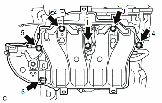
5. INSTALL INTAKE MANIFOLD
(a) Install a new No. 1 intake manifold to head gasket to the intake manifold.
(b) Temporarily install the intake manifold with the 6 bolts.
| (c) Tighten the 6 bolts in the order shown in the illustration. Torque: 21 N·m {214 kgf·cm, 15 ft·lbf} |
|
(d) Connect the purge line hose to the intake manifold, and slide the clamp to secure the hose.
(e) Connect the No. 2 PCV hose to the intake manifold, and slide the clamp to secure the hose.
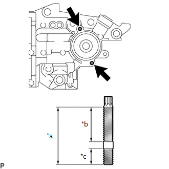
6. INSTALL WATER INLET HOUSING
| (a) Using an E6 "TORX" socket wrench, install the 2 stud bolts to the water inlet housing. Torque: 4.4 N·m {45 kgf·cm, 39 in·lbf} NOTICE: If a stud bolt is deformed or its threads are damaged, replace it. |
|
| (b) Install a new gasket and water inlet housing with the 3 bolts and nut. Torque: 43 N·m {438 kgf·cm, 32 ft·lbf} |
|
7. INSTALL OIL COOLER ASSEMBLY
Click here
8. INSTALL THERMOSTAT
Click here
9. INSTALL WATER INLET
Click here
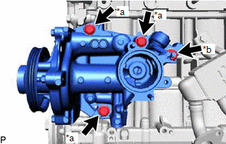
10. INSTALL ENGINE WATER PUMP ASSEMBLY
Click here
11. TEMPORARILY INSTALL NO. 1 EGR PIPE
| (a) Temporarily install the No. 1 EGR pipe with the 2 bolts. |
|
.png)
12. INSTALL NO. 1 WATER BY-PASS HOSE
(a) Install the No. 1 water by-pass hose to the cylinder block, and slide the hose clamp to secure the hose.
13. INSTALL NO. 3 WATER BY-PASS HOSE
(a) Install the No. 3 water by-pass hose, and slide the hose clamp to secure the hose.
14. TEMPORARILY INSTALL EGR VALVE ASSEMBLY
| (a) Install 2 new gaskets to the No. 1 EGR pipe and intake manifold. NOTICE: Make sure that the gasket is installed in the correct direction. |
|

| (b) Temporarily install the No. 1 EGR valve to the intake manifold with the 3 bolts. |
|
.png)
(c) Temporarily connect the No. 1 EGR pipe to the EGR valve assembly with the 2 nuts.
15. TEMPORARILY INSTALL EGR COOLER ASSEMBLY
| (a) Install a new gasket to the No. 1 EGR pipe. NOTICE: Make sure that the gasket is installed in the correct direction. |
|
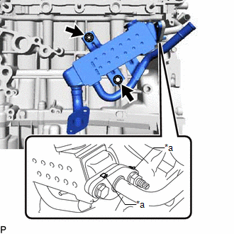
(b) Temporarily install the EGR cooler assembly with the nut and bolt.
HINT:
The nut and bolt can be installed to either side depending on the position of the stud bolt.
(c) Connect the No. 5 water by-pass hose to the EGR cooler assembly, and slide the hose clamp to secure the hose.
(d) Temporarily connect the No. 1 EGR pipe to the EGR cooler assembly with the bolt and nut.
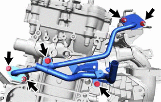
16. INSTALL WATER BY-PASS PIPE
(a) Install 2 new gaskets and the water by-pass pipe with the 4 bolts.
Torque:
10 N·m {102 kgf·cm, 7 ft·lbf}
17. TIGHTEN NO. 1 EGR PIPE
| (a) Tighten the 3 bolts and 3 nuts. Torque: 21 N·m {214 kgf·cm, 15 ft·lbf} |
|
18. TIGHTEN EGR COOLER ASSEMBLY
(a) Tighten the bolt and nut.
Torque:
21 N·m {214 kgf·cm, 15 ft·lbf}
19. TIGHTEN EGR VALVE ASSEMBLY
(a) Tighten the 3 bolts.
Torque:
10 N·m {102 kgf·cm, 7 ft·lbf}
| (b) Connect the No. 1 water by-pass hose and No. 2 water by-pass hose to the EGR valve assembly, and slide the 2 clamps to secure the hose. |
|
.png)
20. INSTALL THROTTLE WITH MOTOR BODY ASSEMBLY
Click here
21. INSTALL EXHAUST MANIFOLD CONVERTER SUB-ASSEMBLY
Click here
22. INSTALL MANIFOLD STAY
Click here
23. INSTALL NO. 2 MANIFOLD STAY
Click here
24. INSTALL NO. 2 EGR PIPE
Click here
25. INSTALL NO. 1 EXHAUST MANIFOLD HEAT INSULATOR
Click here
26. INSTALL NO. 1 COMPRESSOR MOUNTING BRACKET
(a) Install the No. 1 compressor mounting bracket with the 4 bolts.
Torque:
24.5 N·m {250 kgf·cm, 18 ft·lbf}
27. INSTALL COMPRESSOR ASSEMBLY WITH MOTOR
Click here
28. INSTALL V-RIBBED BELT TENSIONER ASSEMBLY
(a) Install the V-ribbed belt tensioner assembly with the bolt.
Torque:
21 N·m {214 kgf·cm, 15 ft·lbf}
29. INSTALL ENGINE OIL LEVEL DIPSTICK GUIDE
(a) Apply a light coat of engine oil to a new O-ring.
(b) Install the O-ring to the engine oil level dipstick guide.
(c) Install the engine oil level dipstick guide with the bolt.
Torque:
10 N·m {102 kgf·cm, 7 ft·lbf}
(d) Install the engine oil level dipstick.
READ NEXT:
 Components
COMPONENTS ILLUSTRATION *1 FRONT SUSPENSION MEMBER REINFORCEMENT RH *2 NO. 1 ENGINE UNDER COVER ASSEMBLY N*m (kgf*cm, ft.*lbf): Specified torque - - ILLUSTRATION *1 CRANK
Removal
REMOVAL PROCEDURE 1. REMOVE NO. 1 ENGINE UNDER COVER ASSEMBLY Click here 2. REMOVE FAN AND GENERATOR V BELT Click here 3. REMOVE FRONT SUSPENSION MEMBER REINFORCEMENT RH Click here 4. REMOVE C
SEE MORE:
Parts Location
PARTS LOCATION ILLUSTRATION *A w/ Rain Sensor *B w/ Sliding Roof System *C w/ Hands Free Power Back Door - - *1 FRONT POWER WINDOW REGULATOR MOTOR ASSEMBLY LH *2 FRONT POWER WINDOW REGULATOR MOTOR ASSEMBLY RH *3 REAR POWER WINDOW REGULATOR MOTOR ASSEMBLY LH *4
Torque Sensor Zero Point Adjustment Undone (C1515,C1516)
DESCRIPTION These DTCs do not indicate a malfunction. The power steering ECU assembly stores C1515 when it determines that torque sensor zero point calibration has not been performed. The power steering ECU assembly stores C1516 when it determines that torque sensor zero point calibration has not co
