Lexus NX: Disassembly
DISASSEMBLY
CAUTION / NOTICE / HINT
NOTICE:
- When using a vise, place aluminum plates between the part and vise.
- When using a vise, do not overtighten it.
PROCEDURE
1. REMOVE STEERING LOCK ACTUATOR ASSEMBLY
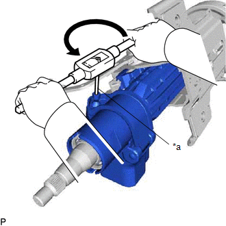
(a) Secure the electric power steering column sub-assembly in a vise.
(b) Using a center punch, mark the center of the tapered-head bolts.
(c) Using a 3 to 4 mm (0.119 to 0.157 in.) diameter drill bit, drill a hole in the tapered-head bolt.
| (d) Using a screw extractor, remove the tapered-head bolt, and then remove the steering lock actuator assembly from the electric power steering column sub-assembly. |
|
2. REMOVE WIRE HARNESS BRACKET
(a) Lift in the direction (1) indicated by the arrow shown in the illustration, and pull in the direction (2) to detach the claw.
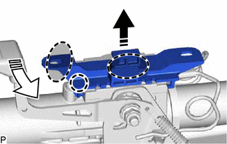
 | Place Hand Here |
.png) | Remove in this Direction (1) |
.png) | Remove in this Direction (2) |
(b) Pull in the direction indicated by the arrow to detach the guide and remove the bracket from the steering column assembly.
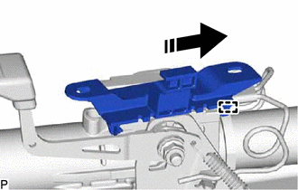
| | Remove in this Direction |
3. REMOVE POWER STEERING ECU ASSEMBLY
Click here .gif)
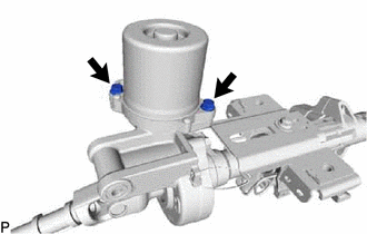
4. REMOVE POWER STEERING MOTOR ASSEMBLY
| (a) Remove the 2 bolts and power steering motor assembly. |
|
READ NEXT:
 Inspection
INSPECTION CAUTION / NOTICE / HINT NOTICE:
When using a vise, place aluminum plates between the part and vise.
When using a vise, do not overtighten it.
PROCEDURE 1. INSPECT ELECTRIC POWER STE
Reassembly
REASSEMBLY CAUTION / NOTICE / HINT NOTICE:
When using a vise, place aluminum plates between the part and vise.
When using a vise, do not overtighten it.
PROCEDURE 1. INSTALL POWER STEERING MOT
Installation
INSTALLATION CAUTION / NOTICE / HINT NOTICE:
Do not replace the spiral with sensor cable sub-assembly with the battery connected and the engine switch on (IG).
Do not rotate the spiral with senso
SEE MORE:
Problem Symptoms Table
PROBLEM SYMPTOMS TABLE HINT:
Inspect the fuses and relays related to this system before inspecting the suspected areas below.
If the problem only occurs in certain locations or at certain times of day, check for wave interference.
If optional components are installed, check for wave interfere
Components
COMPONENTS ILLUSTRATION *A for Driver Side *B for Front Passenger Side *1 FRONT INNER SEAT CUSHION SHIELD LH *2 FRONT LOWER SEAT CUSHION SHIELD *3 FRONT SEAT CUSHION SHIELD LH *4 FRONT SEAT INNER BELT ASSEMBLY LH *5 FRONT SEAT INNER BELT ASSEMBLY RH *6 SEPARAT
