Lexus NX: Inspection
INSPECTION
CAUTION / NOTICE / HINT
NOTICE:
- When using a vise, place aluminum plates between the part and vise.
- When using a vise, do not overtighten it.
PROCEDURE
1. INSPECT ELECTRIC POWER STEERING COLUMN SUB-ASSEMBLY
(a) Secure the electric power steering column sub-assembly in a vise.
| (b) Check that the 2 bushings are securely installed to the electric power steering column sub-assembly. HINT: If the bushings are missing or damaged, replace the electric power steering column sub-assembly with a new one. |
|
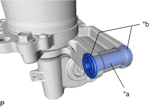
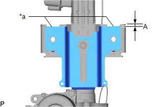
(c) Inspect the capsule.
| (1) Check that the capsule is securely installed to the electric power steering column sub-assembly as shown in the illustration. Standard dimension (A): 4.8 mm (0.189 in.) If the capsule is not positioned as specified, replace the electric power steering column sub-assembly with a new one. |
|
(2) Check the capsule for deformation and damage.
If the capsule is deformed, loose, missing or damaged, replace the electric power steering column sub-assembly with a new one.
READ NEXT:
 Reassembly
REASSEMBLY CAUTION / NOTICE / HINT NOTICE:
When using a vise, place aluminum plates between the part and vise.
When using a vise, do not overtighten it.
PROCEDURE 1. INSTALL POWER STEERING MOT
Installation
INSTALLATION CAUTION / NOTICE / HINT NOTICE:
Do not replace the spiral with sensor cable sub-assembly with the battery connected and the engine switch on (IG).
Do not rotate the spiral with senso
SEE MORE:
Lost Communication with Side Airbag Sensor RH (B1692,B1693,B1697,B1698)
DESCRIPTION The circuit for the side collision sensor LH or RH is composed of the airbag ECU assembly, side airbag sensor assembly LH or RH and door side airbag sensor LH or RH. The side airbag sensor assembly LH or RH and door side airbag sensor LH or RH detect impacts to the vehicle and send signa
Removal
REMOVAL PROCEDURE 1. REMOVE FRONT WIPER ARM HEAD CAP (a) Using a screwdriver, detach the 3 claws and remove the front wiper arm head cap. HINT:
Tape the screwdriver tip before use.
Use the same procedure for both front wiper arm head caps.
*1 Protective Tape 2. REM
