Lexus NX: Inspection
INSPECTION
PROCEDURE
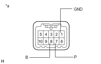
1. INSPECT INTEGRATION CONTROL AND PANEL ASSEMBLY (ABSORBER CONTROL SWITCH)
| (a) Measure the resistance according to the value(s) in the table below. Standard Resistance:
If the result is not as specified, replace the integration control and panel assembly (absorber control switch). |
|
READ NEXT:
 Installation
INSTALLATION PROCEDURE 1. INSTALL INTEGRATION CONTROL AND PANEL ASSEMBLY (ABSORBER CONTROL SWITCH) (a) Install the integration control and panel assembly (absorber control switch) to the upper rear
Precaution
PRECAUTION ADAPTIVE VARIABLE SUSPENSION SYSTEM PRECAUTION NOTICE:
Performing work after replacing the absorber control ECU with a normally functioning one from another vehicle may result in DTCs be
SEE MORE:
Installation
INSTALLATION CAUTION / NOTICE / HINT HINT:
Use the same procedure for RHD and LHD vehicles.
The procedure listed below is for LHD vehicles.
PROCEDURE 1. INSTALL COOLER THERMISTOR (ROOM TEMPERATURE SENSOR) (a) Connect the aspirator hose. (b) Connect the connector. (c) Attach the 2 claws to in
Parts Location
PARTS LOCATION ILLUSTRATION *1 NO. 1 ENGINE ROOM RELAY BLOCK - IG2-MAIN RELAY - IG2-MAIN FUSE - STRG LOCK FUSE - - ILLUSTRATION *1 POWER SWITCH *2 INSTRUMENT PANEL JUNCTION BLOCK ASSEMBLY - IG2 NO. 3 FUSE *3 MAIN BODY ECU (MULTIPLEX NETWORK BODY ECU) *4 DLC3 *5
© 2016-2026 Copyright www.lexunx.com
