Lexus NX: Disassembly
DISASSEMBLY
CAUTION / NOTICE / HINT
HINT:
- Use the same procedure for the RH and LH side.
- The procedure listed below is for the LH side.
PROCEDURE
1. PRECAUTION
CAUTION:
Be sure to read Precaution thoroughly before servicing.
Click here .gif)
NOTICE:
After turning the power switch off, waiting time may be required before disconnecting the cable from the auxiliary battery negative (-) terminal.
Click here
2. REMOVE NO. 3 DECK BOARD SUB-ASSEMBLY
Click here
3. REMOVE REAR DECK FLOOR BOX
Click here
4. REMOVE DECK FLOOR BOX LH
Click here
5. DISCONNECT CABLE FROM NEGATIVE AUXILIARY BATTERY TERMINAL
CAUTION:
Wait at least 90 seconds after disconnecting the cable from the auxiliary battery negative (-) terminal to disable the SRS system.
6. REMOVE FRONT DOOR TRIM COVER LH
| (a) Remove the front door trim cover LH. |
|
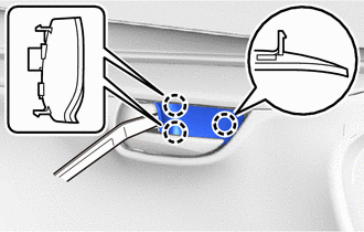
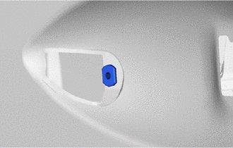
7. REMOVE FRONT DOOR INSIDE HANDLE BEZEL PLUG LH
| (a) Using moulding remover A, detach the 3 claws and remove the front door inside handle bezel plug LH. |
|
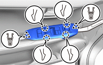
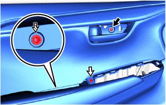
8. REMOVE POWER WINDOW REGULATOR MASTER SWITCH ASSEMBLY WITH FRONT DOOR ARMREST BASE PANEL (for Driver Side)
| (a) Using moulding remover A, detach the 2 clips, 4 claws and remove the power window regulator master switch assembly with front door armrest base panel. |
|
| (b) Disconnect the 2 connectors. |
|
9. REMOVE POWER WINDOW REGULATOR SWITCH ASSEMBLY WITH FRONT DOOR ARMREST BASE PANEL (for Front Passenger Side)
| (a) Using moulding remover A, detach the 2 clips, 4 claws and remove the power window regulator switch assembly with front door armrest base panel. |
|
| (b) Disconnect the 2 connectors. |
|
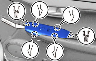
10. REMOVE FRONT DOOR TRIM BOARD SUB-ASSEMBLY LH
(a) Remove the screw labeled A.
.png) | Screw A |
.png) | Screw B |
 | Screw C |
(b) Remove the screw labeled B.
(c) Remove the screw labeled C.
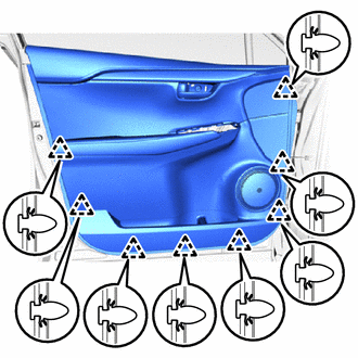
| (d) Detach the 8 clips and remove the front door trim board sub-assembly LH. |
|
(e) for Driver Side with Memory:
(1) Disconnect the connector.
| (f) Detach the 2 clamps. |
|
(g) Disconnect the front door lock remote control cable assembly LH and front door inside locking cable assembly LH from the front door trim board sub-assembly LH.
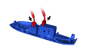
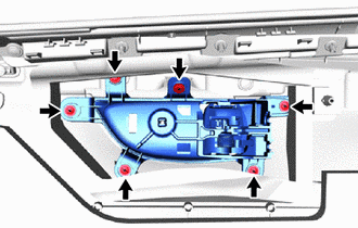
11. REMOVE FRONT DOOR INSIDE HANDLE SUB-ASSEMBLY LH
| (a) Remove the 6 screws and front door inside handle sub-assembly LH. |
|
12. REMOVE SEAT MEMORY SWITCH (for Driver Side with Memory)
Click here
13. REMOVE FRONT SEAT SLIDE SWITCH BEZEL (for Driver Side with Memory)
Click here
14. REMOVE FRONT DOOR INNER GLASS WEATHERSTRIP LH
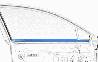
(a) Remove the front door inner glass weatherstrip LH.
15. REMOVE FRONT DOOR ARMREST SET BRACKET LH
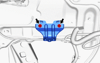
(a) Remove the 2 screws and front door armrest set bracket LH.
16. REMOVE OUTER MIRROR CONTROL ECU ASSEMBLY
Click here
17. REMOVE OUTER MIRROR INSTALL HOLE COVER LH
Click here
18. REMOVE OUTER REAR VIEW MIRROR ASSEMBLY LH
Click here
19. REMOVE FRONT NO. 1 SPEAKER ASSEMBLY
Click here
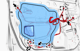
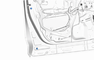
20. REMOVE FRONT DOOR SERVICE HOLE COVER LH
(a) Disconnect the 3 connectors.
(b) Remove the bolt and disconnect the ground wire.
(c) Detach the 3 clamps, move the wire harness out of the way and remove the front door service hole cover LH.
HINT:
Remove any remaining butyl tape from the door.
| | Connector |
| | Bolt |
21. REMOVE DOOR SIDE AIR BAG SENSOR LH
Click here
22. REMOVE FRONT DOOR GLASS RUN LH
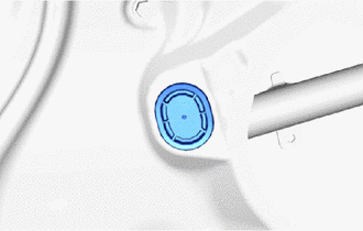
| (a) Remove the hole plug. |
|
(b) Temporarily install the power window regulator master switch assembly with front door armrest base panel.
(c) Connect the cable to the auxiliary battery negative (-) terminal.
(d) Move the front door window regulator so that the front door glass bolts can be seen.
(e) Disconnect the cable from the auxiliary battery negative (-) terminal.
CAUTION:
Wait at least 90 seconds after disconnecting the cable from the auxiliary battery negative (-) terminal to disable the SRS system.
NOTICE:
When disconnecting the cable, some systems need to be initialized after the cable is reconnected.
Click here
(f) Remove the power window regulator master switch assembly with front door armrest base panel.
| (g) Remove the front door glass run LH. |
|
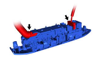
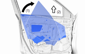
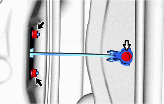
23. REMOVE FRONT DOOR GLASS SUB-ASSEMBLY LH
| (a) Remove the 2 bolts. NOTICE: After the bolts are removed, do not allow the front door glass to fall. |
|
| (b) Remove the front door glass sub-assembly LH as indicated by the arrows in the order shown in the illustration. NOTICE: Do not damage the front door glass. |
|
24. REMOVE FRONT DOOR FRONT LOWER FRAME SUB-ASSEMBLY LH
(a) Lift up the weatherstrip and remove the screw.
| | Bolt |
| | Screw |
(b) Remove the 3 bolts and front door front lower frame sub-assembly LH.
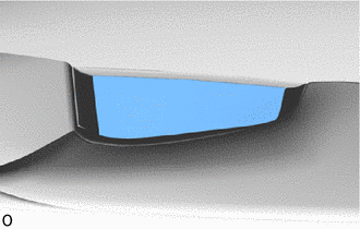
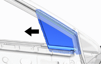
25. REMOVE FRONT DOOR FIX WINDOW GLASS LH
| (a) Remove the front door fix window glass LH in the direction indicated by the arrow in the illustration. |
|
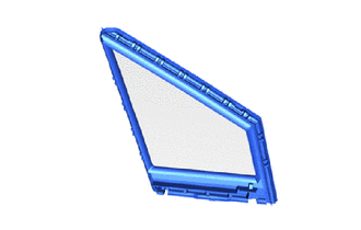
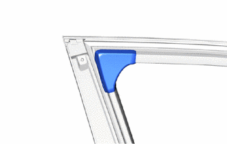
26. REMOVE FRONT DOOR FIX WINDOW WEATHERSTRIP LH
| (a) Remove the front door fix window weatherstrip LH. |
|
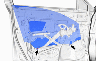
27. REMOVE FRONT DOOR WINDOW REGULATOR SUB-ASSEMBLY LH
| (a) Loosen the temporarily bolt. NOTICE: Do not remove the temporarily bolt. If the temporarily bolt is removed, the front door window regulator sub-assembly LH may fall and become damaged. |
|
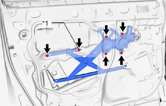
(b) Remove the 5 bolts and front door window regulator sub-assembly LH.
(c) Remove the temporarily bolt from the front door window regulator sub-assembly LH.
28. REMOVE FRONT DOOR NO. 1 STIFFENER CUSHION
(a) Remove the 2 bolts, double-sided tape and front door No. 1 stiffener cushion.
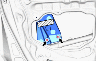
 | Double-sided Tape |
NOTICE:
Remove any remaining tape from the door.
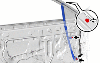
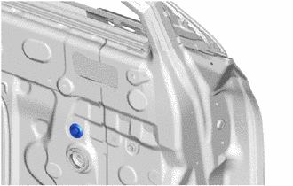
29. REMOVE FRONT DOOR REAR LOWER FRAME SUB-ASSEMBLY LH
| (a) Remove the bolt. |
|
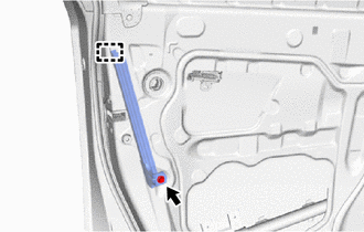
(b) Detach the guide and remove the front door rear lower frame sub-assembly LH.
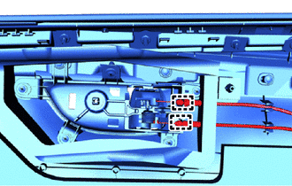
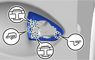
30. REMOVE FRONT DOOR OUTSIDE HANDLE ASSEMBLY LH
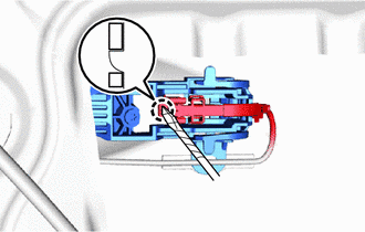
(a) Using a screwdriver, detach the 2 claws of the connector cover in the direction indicated and disconnect the connector cover.
HINT:
Tape the screwdriver tip before use.
| | Protective Tape |
(b) Using a screwdriver, detach the claw of the connector in the direction indicated and disconnect the connector.
HINT:
Tape the screwdriver tip before use.
| | Protective Tape |
| (c) Detach the 2 claws and remove the holder in the direction indicated by the arrow in the illustration. |
|
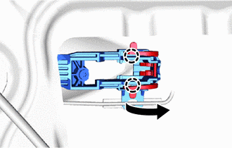
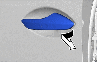
| (d) Remove the front door outside handle assembly LH by sliding and pulling it in the direction indicated by the arrow in the illustration. |
|
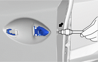
31. REMOVE FRONT DOOR LOCK CYLINDER ASSEMBLY LH (for Driver Side)
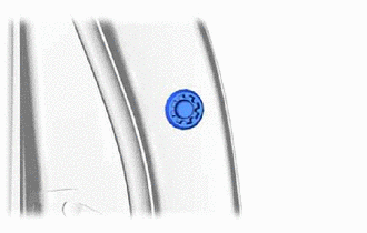
| (a) Remove the hole plug. |
|
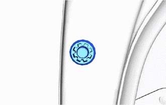
| (b) Using a T30 "TORX" socket wrench, loosen the screw and remove the front door lock cylinder assembly LH. |
|
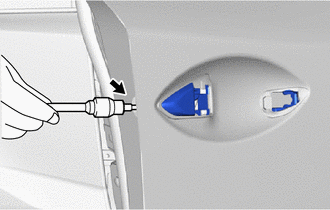
32. REMOVE FRONT DOOR OUTSIDE HANDLE COVER RH (for Front Passenger Side)
| (a) Remove the hole plug. |
|
| (b) Using a T30 "TORX" socket wrench, loosen the screw and remove the front door outside handle cover RH. |
|
33. REMOVE FRONT DOOR FRONT OUTSIDE HANDLE PAD
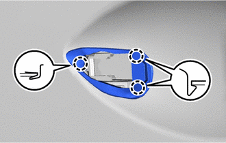
(a) Detach the 3 claws and remove the front door front outside handle pad.
34. REMOVE FRONT DOOR REAR OUTSIDE HANDLE PAD
(a) Detach the 4 claws and remove the front door rear outside handle pad.
35. REMOVE FRONT DOOR OUTSIDE HANDLE FRAME SUB-ASSEMBLY LH
| (a) Using a T30 "TORX" socket wrench, loosen the screw. |
|
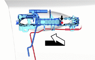
(b) Disconnect the front door outside handle frame sub-assembly LH with wire in the direction indicated by the arrow in the illustration.
| (c) Detach the clamp and remove the front door outside handle frame sub-assembly LH. |
|
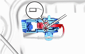
36. REMOVE FRONT DOOR LOCK OPEN ROD LH
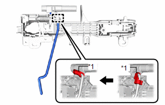
| *1 | Snap |
(a) Disconnect the snap and remove the front door lock open rod LH as shown in the illustration.
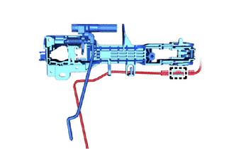
37. REMOVE DOOR OUTSIDE HANDLE BUSH
| (a) Remove the door outside handle bush. |
|
38. REMOVE FRONT DOOR LOCK ASSEMBLY LH
Click here
39. REMOVE FRONT DOOR CHECK ASSEMBLY LH
(a) Remove the bolt, 2 nuts and front door check assembly LH.
| | Nut |
| | Bolt |
40. REMOVE UPPER DOOR FRAME GARNISH LH
| (a) Remove the upper door frame garnish LH. |
|
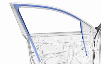
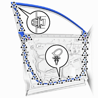
41. REMOVE FRONT DOOR WEATHERSTRIP LH
| (a) Using a clip remover, detach the 24 clips and remove the front door weatherstrip LH. |
|
42. REMOVE FRONT DOOR LOWER OUTSIDE MOULDING SUB-ASSEMBLY LH
Click here
43. REMOVE FRONT DOOR UPPER OUTSIDE MOULDING PAD
Click here
44. REMOVE FRONT DOOR BELT MOULDING ASSEMBLY LH
Click here
45. REMOVE FRONT DOOR PANEL CUSHION
| (a) Detach the 2 front door panel cushions. |
|
46. REMOVE HOLE PLUG
| (a) Remove the hole plug. |
|
47. REMOVE FRONT DOOR REAR WINDOW FRAME MOULDING LH
Click here
48. REMOVE FRONT DOOR OUTSIDE MOULDING SUB-ASSEMBLY LH
Click here
49. REMOVE NO. 3 BLACK OUT TAPE LH
Click here
50. REMOVE NO. 2 BLACK OUT TAPE LH
Click here
51. REMOVE NO. 1 BLACK OUT TAPE LH
Click here
READ NEXT:
 Inspection
INSPECTION PROCEDURE 1. INSPECT FRONT DOOR OUTSIDE HANDLE ASSEMBLY LH (a) Check that the LED illuminates. (1) Apply 6.0 V (4 dry cell batteries in series) to each terminal and check the illuminatio
Adjustment
ADJUSTMENT CAUTION / NOTICE / HINT HINT:
Use the same procedure for the RH and LH sides.
The procedure listed below is for the LH side.
Centering bolts are used to mount the door hinge to the v
Reassembly
REASSEMBLY CAUTION / NOTICE / HINT HINT:
Use the same procedure for the RH and LH side.
The procedure listed below is for the LH side.
A bolt without a torque specification is shown in the stan
SEE MORE:
Terminals Of Ecu
TERMINALS OF ECU CHECK MULTIPLEX NETWORK MASTER SWITCH ASSEMBLY (a) Disconnect the M10 multiplex network master switch assembly connector. (b) Measure the voltage and resistance according to the value(s) in the table below. HINT: Measure the values on the wire harness side with the connector discon
Problem Symptoms Table
PROBLEM SYMPTOMS TABLE HINT:
Use the table below to help determine the cause of problem symptoms. If multiple suspected areas are listed, the potential causes of the symptoms are listed in order of probability in the "Suspected Area" column of the table. Check each symptom by checking the suspect
