Lexus NX: Terminals Of Ecu
TERMINALS OF ECU
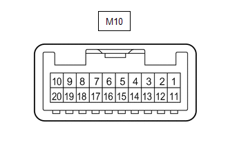
CHECK MULTIPLEX NETWORK MASTER SWITCH ASSEMBLY
(a) Disconnect the M10 multiplex network master switch assembly connector.
(b) Measure the voltage and resistance according to the value(s) in the table below.
HINT:
Measure the values on the wire harness side with the connector disconnected.
| Tester Connection | Wiring Color | Terminal Description | Condition | Specified Condition |
|---|---|---|---|---|
| M10-11 (B) - M10-12 (GND) | SB - W-B | Power supply | Power switch off | 11 to 14 V |
| M10-12 (GND) - Body ground | W-B - Body ground | Ground | Always | Below 1 Ω |
(c) Reconnect the M10 multiplex network master switch assembly connector.
(d) Measure the voltage according to the value(s) in the table below.
| Tester Connection | Wiring Color | Terminal Description | Condition | Specified Condition |
|---|---|---|---|---|
| M10-15 (DOWN) - M10-12 (GND) | B - W-B | Power window motor DOWN output | Power switch on (IG), driver door power window regulator switch not pushed or pulled | 11 to 14 V |
| Power switch on (IG), driver door power window moving, driver door power window regulator switch pushed halfway down (Manual operation) | Below 1 V | |||
| M10-20 (UP) - M10-12 (GND) | LG - W-B | Power window motor UP output | Power switch on (IG), driver door power window regulator switch not pushed or pulled | 11 to 14 V |
| Power switch on (IG), driver door power window moving, driver door power window regulator switch pulled halfway up (Manual operation) | Below 1 V |
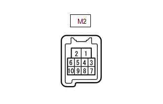
CHECK FRONT POWER WINDOW REGULATOR MOTOR ASSEMBLY LH
(a) Disconnect the M2 front power window regulator motor assembly LH connector.
(b) Measure the voltage and resistance according to the value(s) in the table below.
HINT:
Measure the values on the wire harness side with the connector disconnected.
| Tester Connection | Wiring Color | Terminal Description | Condition | Specified Condition |
|---|---|---|---|---|
| M2-1 (GND) - Body ground | W-B - Body ground | Ground | Always | Below 1 Ω |
| M2-2 (B) - Body ground | P - Body ground | Power supply | Power switch off | 11 to 14 V |
(c) Reconnect the M2 front power window regulator motor assembly LH connector.
(d) Measure the voltage according to the value(s) in the table below.
| Tester Connection | Wiring Color | Terminal Description | Condition | Specified Condition |
|---|---|---|---|---|
| M2-7 (DOWN) - M2-1 (GND) | B - W-B | Power window motor DOWN input | Power switch on (IG), multiplex network master switch assembly (driver door power window regulator switch) not pushed or pulled | 11 to 14 V |
| Power switch on (IG), driver door power window moving, multiplex network master switch assembly (driver door power window regulator switch) pushed halfway down (Manual operation) | Below 1 V | |||
| Power switch on (IG), driver door power window fully closed | 11 to 14 V | |||
| Power switch on (IG), driver door power window moving, multiplex network master switch assembly (driver door power window regulator switch) fully pushed down (Auto operation) | Below 1 V | |||
| Power switch on (IG), driver door power window fully open | 11 to 14 V | |||
| M2-10 (UP) - M2-1 (GND) | LG - W-B | Power window motor UP input | Power switch on (IG), multiplex network master switch assembly (driver door power window regulator switch) not pushed or pulled | 11 to 14 V |
| Power switch on (IG), driver door power window moving, multiplex network master switch assembly (driver door power window regulator switch) pulled halfway up (Manual operation) | Below 1 V | |||
| Power switch on (IG), driver door power window fully opened | 11 to 14 V | |||
| Power switch on (IG), driver door power window moving, multiplex network master switch assembly (driver door power window regulator switch) fully pulled up (Auto operation) | Below 1 V | |||
| Power switch on (IG), driver door power window fully closed | 11 to 14 V |
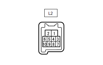
CHECK FRONT POWER WINDOW REGULATOR MOTOR ASSEMBLY RH
(a) Disconnect the L2 front power window regulator motor assembly RH connector.
(b) Measure the voltage and resistance according to the value(s) in the table below.
HINT:
Measure the values on the wire harness side with the connector disconnected.
| Tester Connection | Wiring Color | Terminal Description | Condition | Specified Condition |
|---|---|---|---|---|
| L2-1 (GND) - Body ground | W-B - Body ground | Ground | Always | Below 1 Ω |
| L2-2 (B) - Body ground | G - Body ground | Power supply | Power switch off | 11 to 14 V |
(c) Reconnect the L2 front power window regulator motor assembly RH connector.
(d) Measure the voltage according to the value(s) in the table below.
| Tester Connection | Wiring Color | Terminal Description | Condition | Specified Condition |
|---|---|---|---|---|
| L2-4 (AUTO) - L2-1 (GND) | Y - W-B | Power window motor AUTO UP input | Power switch on (IG), front passenger door power window fully open | 11 to 14 V |
| Power switch on (IG), front passenger door power window moving, power window regulator switch assembly fully pulled up (Auto operation) | Below 1 V | |||
| Power switch on (IG), front passenger door power window fully closed | 11 to 14 V | |||
| Power window motor AUTO DOWN input | Power switch on (IG), front passenger door power window fully closed | 11 to 14 V | ||
| Power switch on (IG), front passenger door power window moving, power window regulator switch assembly fully pushed down (Auto operation) | Below 1 V | |||
| Power switch on (IG), front passenger door power window fully open | 11 to 14 V | |||
| L2-7 (DOWN) - L2-1 (GND) | B - W-B | Power window motor DOWN input | Power switch on (IG), power window regulator switch assembly not pushed or pulled | 11 to 14 V |
| Power switch on (IG), front passenger door power window moving, power window regulator switch assembly pushed halfway down (Manual operation) | Below 1 V | |||
| Power switch on (IG), front passenger door power window fully closed | 11 to 14 V | |||
| Power switch on (IG), front passenger door power window moving, power window regulator switch assembly fully pushed down (Auto operation) | Below 1 V | |||
| Power switch on (IG), front passenger door power window fully open | 11 to 14 V | |||
| L2-10 (UP) - L2-1 (GND) | R - W-B | Power window motor UP input | Power switch on (IG), power window regulator switch assembly not pushed or pulled | 11 to 14 V |
| Power switch on (IG), front passenger door power window moving, power window regulator switch assembly pulled halfway up (Manual operation) | Below 1 V | |||
| Power switch on (IG), front passenger door power window fully open | 11 to 14 V | |||
| Power switch on (IG), front passenger door power window moving, power window regulator switch assembly fully pulled up (Auto operation) | Below 1 V | |||
| Power switch on (IG), front passenger door power window fully closed | 11 to 14 V |
CHECK REAR POWER WINDOW REGULATOR MOTOR ASSEMBLY LH
(a) Disconnect the O2 rear power window regulator motor assembly LH connector.

(b) Measure the voltage and resistance according to the value(s) in the table below.
HINT:
Measure the values on the wire harness side with the connector disconnected.
| Tester Connection | Wiring Color | Terminal Description | Condition | Specified Condition |
|---|---|---|---|---|
| O2-1 (GND) - Body ground | W-B - Body ground | Ground | Always | Below 1 Ω |
| O2-2 (B) - Body ground | LA-Y - Body ground | Power supply | Power switch off | 11 to 14 V |
(c) Reconnect the O2 rear power window regulator motor assembly LH connector.
(d) Measure the voltage according to the value(s) in the table below.
| Tester Connection | Wiring Color | Terminal Description | Condition | Specified Condition |
|---|---|---|---|---|
| O2-4 (AUTO) - O2-1 (GND) | G - W-B | Power window motor AUTO UP input | Power switch on (IG), rear LH door power window fully open | 11 to 14 V |
| Power switch on (IG), rear LH door power window moving, rear power window regulator switch assembly (for rear LH door) fully pulled up (Auto operation) | Below 1 V | |||
| Power switch on (IG), rear LH door power window fully closed | 11 to 14 V | |||
| Power window motor AUTO DOWN input | Power switch on (IG), rear LH door power window fully closed | 11 to 14 V | ||
| Power switch on (IG), rear LH door power window moving, rear power window regulator switch assembly (for rear LH door) fully pushed down (Auto operation) | Below 1 V | |||
| Power switch on (IG), rear LH door power window fully open | 11 to 14 V | |||
| O2-7 (DOWN) - O2-1 (GND) | W - W-B | Power window motor DOWN input | Power switch on (IG), rear power window regulator switch assembly (for rear LH door) not pushed or pulled | 11 to 14 V |
| Power switch on (IG), rear LH door power window moving, rear power window regulator switch assembly (for rear LH door) pushed halfway down (Manual operation) | Below 1 V | |||
| Power switch on (IG), rear LH door power window fully closed | 11 to 14 V | |||
| Power switch on (IG), rear LH door power window moving, rear power window regulator switch assembly (for rear LH door) fully pushed down (Auto operation) | Below 1 V | |||
| Power switch on (IG), rear LH door power window fully open | 11 to 14 V | |||
| O2-10 (UP) - O2-1 (GND) | L - W-B | Power window motor UP input | Power switch on (IG), rear power window regulator switch assembly (for rear LH door) not pushed or pulled | 11 to 14 V |
| Power switch on (IG), rear LH door power window moving, rear power window regulator switch assembly (for rear LH door) pulled halfway up (Manual operation) | Below 1 V | |||
| Power switch on (IG), rear LH door power window fully open | 11 to 14 V | |||
| Power switch on (IG), rear LH door power window moving, rear power window regulator switch assembly (for rear LH door) fully pulled up (Auto operation) | Below 1 V | |||
| Power switch on (IG), rear LH door power window fully closed | 11 to 14 V |
CHECK REAR POWER WINDOW REGULATOR MOTOR ASSEMBLY RH
(a) Disconnect the N2 rear power window regulator motor assembly RH connector.

(b) Measure the voltage and resistance according to the value(s) in the table below.
HINT:
Measure the values on the wire harness side with the connector disconnected.
| Tester Connection | Wiring Color | Terminal Description | Condition | Specified Condition |
|---|---|---|---|---|
| N2-1 (GND) - Body ground | W-B - Body ground | Ground | Always | Below 1 Ω |
| N2-2 (B) - Body ground | LA-G - Body ground | Power supply | Power switch off | 11 to 14 V |
(c) Reconnect the N2 rear power window regulator motor assembly RH connector.
(d) Measure the voltage according to the value(s) in the table below.
| Tester Connection | Wiring Color | Terminal Description | Condition | Specified Condition |
|---|---|---|---|---|
| N2-4 (AUTO) - N2-1 (GND) | B - W-B | Power window motor AUTO UP input | Power switch on (IG), rear RH door power window fully open | 11 to 14 V |
| Power switch on (IG), rear RH door power window moving, rear power window regulator switch assembly (for rear RH door) fully pulled up (Auto operation) | Below 1 V | |||
| Power switch on (IG), rear RH door power window fully closed | 11 to 14 V | |||
| Power window motor AUTO DOWN input | Power switch on (IG), rear RH door power window fully closed | 11 to 14 V | ||
| Power switch on (IG), rear RH door power window moving, rear power window regulator switch assembly (for rear RH door) fully pushed down (Auto operation) | Below 1 V | |||
| Power switch on (IG), rear RH door power window fully open | 11 to 14 V | |||
| N2-7 (DOWN) - N2-1 (GND) | W - W-B | Power window motor DOWN input | Power switch on (IG), rear power window regulator switch assembly (for rear RH door) not pushed or pulled | 11 to 14 V |
| Power switch on (IG), rear RH door power window moving, rear power window regulator switch assembly (for rear RH door) pushed halfway down (Manual operation) | Below 1 V | |||
| Power switch on (IG), rear RH door power window fully closed | 11 to 14 V | |||
| Power switch on (IG), rear RH door power window moving, rear power window regulator switch assembly (for rear RH door) fully pushed down (Auto operation) | Below 1 V | |||
| Power switch on (IG), rear RH door power window fully open | 11 to 14 V | |||
| N2-10 (UP) - N2-1 (GND) | V - W-B | Power window motor UP input | Power switch on (IG), rear power window regulator switch assembly (for rear RH door) not pushed or pulled | 11 to 14 V |
| Power switch on (IG), rear RH door power window moving, rear power window regulator switch assembly (for rear RH door) pulled halfway up (Manual operation) | Below 1 V | |||
| Power switch on (IG), rear RH door power window fully open | 11 to 14 V | |||
| Power switch on (IG), rear RH door power window moving, rear power window regulator switch assembly (for rear RH door) fully pulled up (Auto operation) | Below 1 V | |||
| Power switch on (IG), rear RH door power window fully closed | 11 to 14 V |
CHECK INSTRUMENT PANEL JUNCTION BLOCK ASSEMBLY AND MAIN BODY ECU (MULTIPLEX NETWORK BODY ECU)
.png)
| *1 | Main Body ECU (Multiplex Network Body ECU) | - | - |
(a) Remove the main body ECU (multiplex network body ECU) from the instrument panel junction block assembly.
Click here .gif)
(b) Measure the voltage and resistance according to the value(s) in the table below.
| Tester Connection | Wiring Color | Terminal Description | Condition | Specified Condition |
|---|---|---|---|---|
| A-11 (GND1) - Body ground | None - Body ground | Ground | Always | Below 1 Ω |
| A-31 (BECU) - Body ground | None - Body ground | Auxiliary battery power supply | Power switch off | 11 to 14 V |
| A-30 (ACC) - Body ground | None - Body ground | ACC power supply | Power switch on (ACC) | 11 to 14 V |
| Power switch off | Below 1 V | |||
| A-32 (IG) - Body ground | None - Body ground | IG power supply | Power switch on (IG) | 11 to 14 V |
| Power switch off | Below 1 V |
(c) Install the main body ECU (multiplex network body ECU) to the instrument panel junction block assembly.
Click here
(d) Measure the voltage and waveform according to the value(s) in the table below.
| Tester Connection | Wiring Color | Terminal Description | Condition | Specified Condition |
|---|---|---|---|---|
| I48-6 (FLCY) - Body ground | G - Body ground | Front door courtesy light switch assembly LH input | Front door LH open | Below 1 V |
| Front door LH closed | Pulse generation | |||
| I48-27 (FRCY) - Body ground | W - Body ground | Front door courtesy light switch assembly RH input | Front door RH open | Below 1 V |
| Front door RH closed | Pulse generation | |||
| I48-29 (L2) - Body ground | R - Body ground | Driver door key-linked lock input | Driver door key cylinder turned to lock | Below 1 V |
| Driver door key cylinder off | Pulse generation | |||
| I48-2 (UL3) - Body ground | LG - Body ground | Driver door key-linked unlock input | Driver door key cylinder turned to unlock | Below 1 V |
| Driver door key cylinder off | Pulse generation |
READ NEXT:
 Dtc Check / Clear
DTC CHECK / CLEAR CHECK DTC (a) Turn the power switch off. (b) Connect the Techstream to the DLC3. (c) Turn the power switch on (IG). (d) Turn the Techstream on. (e) Enter the following menus: Body El
Fail-safe Chart
FAIL-SAFE CHART PULSE FAILURE (a) If the pulse sensor malfunctions, the following power window operations are prohibited. Multiplex Network Master Switch Assembly, Power Window Regulator Switch Assemb
Data List / Active Test
DATA LIST / ACTIVE TEST DATA LIST HINT: Using the Techstream to read the Data List allows the values or states of switches, sensors, actuators and other items to be read without removing any parts. Th
SEE MORE:
How To Proceed With Troubleshooting
CAUTION / NOTICE / HINT HINT:
Use the following procedure to troubleshoot the automatic high beam system.
*: Use the Techstream.
PROCEDURE 1. VEHICLE BROUGHT TO WORKSHOP
NEXT 2. INSPECT AUXILIARY BATTERY VOLTAGE (a) Measure the auxiliary battery voltage wit
Parts Location
PARTS LOCATION ILLUSTRATION *1 INNER REAR VIEW MIRROR ASSEMBLY *2 OUTER REAR VIEW MIRROR ASSEMBLY LH *3 OUTER REAR VIEW MIRROR ASSEMBLY RH *4 OUTER MIRROR LH *5 OUTER MIRROR RH *6 OUTER MIRROR CONTROL ECU ASSEMBLY LH *7 OUTER MIRROR CONTROL ECU ASSEMBLY RH *8
