Lexus NX: Inspection
INSPECTION
PROCEDURE
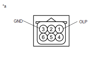
1. INSPECT FRONT DOOR OUTSIDE HANDLE ASSEMBLY LH
| (a) Check that the LED illuminates. (1) Apply 6.0 V (4 dry cell batteries in series) to each terminal and check the illumination state of the light. OK:
NOTICE: Do not apply more than 6.0 V. If the result is not as specified, replace the front door outside handle assembly LH. |
|
2. INSPECT FRONT DOOR OUTSIDE HANDLE ASSEMBLY RH
| (a) Check that the LED illuminates. (1) Apply 6.0 V (4 dry cell batteries in series) to each terminal and check the illumination state of the light. OK:
NOTICE: Do not apply more than 6.0 V. If the result is not as specified, replace the front door outside handle assembly RH. |
|
READ NEXT:
 Adjustment
ADJUSTMENT CAUTION / NOTICE / HINT HINT:
Use the same procedure for the RH and LH sides.
The procedure listed below is for the LH side.
Centering bolts are used to mount the door hinge to the v
Reassembly
REASSEMBLY CAUTION / NOTICE / HINT HINT:
Use the same procedure for the RH and LH side.
The procedure listed below is for the LH side.
A bolt without a torque specification is shown in the stan
Front Door Opening Trim Weatherstrip
ComponentsCOMPONENTS ILLUSTRATION *1 DOOR SCUFF PLATE ASSEMBLY LH *2 FRONT DOOR OPENING TRIM WEATHERSTRIP LH RemovalREMOVAL CAUTION / NOTICE / HINT HINT:
Use the same procedure for t
SEE MORE:
Parts Location
PARTS LOCATION ILLUSTRATION *1 AIR CONDITIONING CONTROL ASSEMBLY - REAR WINDOW DEFOGGER SWITCH *2 INSTRUMENT PANEL JUNCTION BLOCK ASSEMBLY - ECU-IG NO.1 FUSE - ECU-IG NO.3 FUSE *3 DLC3 - - ILLUSTRATION *1 DEFOGGER RELAY *2 AIR CONDITIONING AMPLIFIER ASSEMBLY *3
Open in Turn Signal Circuit (B1507,B1508)
DESCRIPTION These DTCs are stored when the combination meter assembly detects an open in a turn signal light circuit, a short in a turn signal light circuit, or a short in the hazard warning light circuit. DTC No. Detection Item DTC Detection Condition Trouble Area B1507 Open in Turn
