Lexus NX: Disassembly
DISASSEMBLY
PROCEDURE
1. REMOVE GLOVE COMPARTMENT DOOR CHECK CUSHION
HINT:
Use the same procedure for both glove compartment door check cushions.
| (a) Using a screwdriver, detach the 3 claws and remove the glove compartment door check cushion. HINT: Tape the screwdriver tip before use. |
|
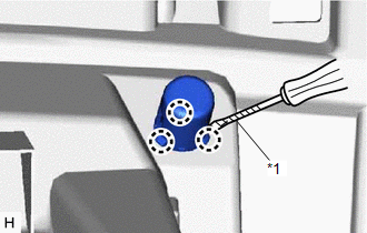
2. REMOVE GLOVE BOX LIGHT ASSEMBLY
Click here .gif)
3. REMOVE GLOVE COMPARTMENT DOOR LOCK CYLINDER ASSEMBLY
NOTICE:
Perform this procedure only when replacement of the glove compartment door assembly is necessary.
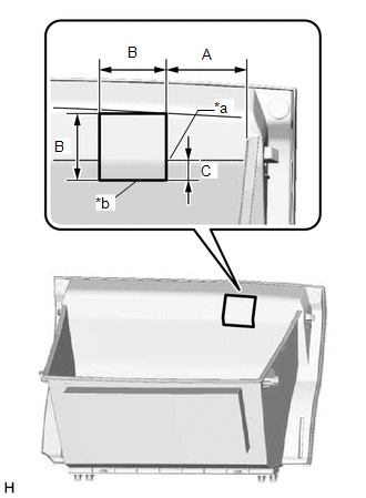
| (a) Mark the glove compartment door assembly as shown in the illustration. Standard Measurement
|
|
(b) Insert a 3.0 mm (0.118 in.) drill bit into a drill.
(c) Tape the 3.0 mm (0.118 in.) drill bit 10.0 mm (0.394 in.) from the tip as shown in the illustration.
NOTICE:
Tape the 3.0 mm (0.118 in.) drill bit to prevent the drill bit from going too deep.
(d) Drill holes along the marking as shown in the illustration.
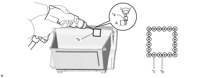
| *a | Tape | *b | Marking |
| *c | Drilled Hole | - | - |
| Area | Area |
|---|---|
| A | 10.0 mm (0.394 in.) |
CAUTION:
- In order to avoid injury, make sure to work carefully so that the tip of the drill does not slip.
- Make sure to wear protective glasses when performing this procedure as shavings will fly about.
NOTICE:
To prevent the glove compartment lock cylinder assembly from being damaged, make sure to only drill holes along the marking.
(e) Insert a 7.0 mm (0.276 in.) drill bit into a drill.
(f) Tape the 7.0 mm (0.276 in.) drill bit 10.0 mm (0.394 in.) from the tip as shown in the illustration.
NOTICE:
Tape the 7.0 mm (0.276 in.) drill bit to prevent the drill bit from going too deep.
(g) Redrill each hole using the 7.0 mm (0.276 in.) drill bit.
CAUTION:
- In order to avoid injury, make sure to center the tip of the drill in the pilot hole so that the tip of the drill does not slip.
- Make sure to wear protective glasses when performing this procedure as shavings will fly about.
(h) Using a plier nipper (side cutters), cut the glove compartment door assembly between each hole.
(i) Using a nipper, cut the position shown in the illustration and disconnect the backside of the holder.
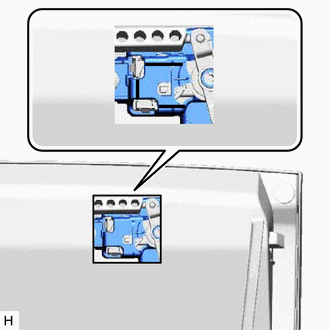
 | Disconnection Position |
(j) Press the cylinder lock to release it and pull out the glove compartment door lock cylinder assembly from the glove compartment door assembly to remove it as shown in the illustration.
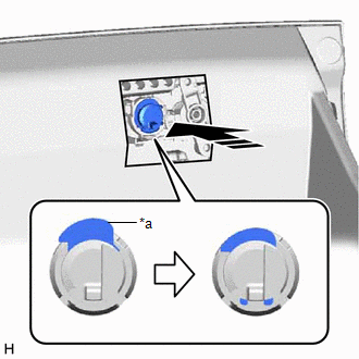
| *a | Cylinder Lock |
 | Remove in this Direction |
READ NEXT:
 Reassembly
REASSEMBLY PROCEDURE 1. INSTALL GLOVE COMPARTMENT DOOR LOCK CYLINDER ASSEMBLY (a) With the cylinder lock pressed, insert the glove compartment door lock cylinder assembly into the glove compartment do
Installation
INSTALLATION CAUTION / NOTICE / HINT HINT: A bolt without a torque specification is shown in the standard bolt chart. Click here PROCEDURE 1. INSTALL LOWER INSTRUMENT PANEL SUB-ASSEMBLY (a) Cut off
SEE MORE:
Customize Parameters
CUSTOMIZE PARAMETERS CUSTOMIZE SLIDING ROOF SYSTEM HINT: The following items can be customized. NOTICE:
When the customer requests a change in a function, first make sure that the function can be customized.
Be sure to make notes of the current settings before customizing.
When troubleshootin
Data List / Active Test
DATA LIST / ACTIVE TEST DATA LIST HINT: Using the Techstream to read the Data List allows the values or states of switches, sensors, actuators and other items to be read without removing any parts. This non-intrusive inspection can be very useful because intermittent conditions or signals may be dis
