Lexus NX: Installation
INSTALLATION
CAUTION / NOTICE / HINT
HINT:
A bolt without a torque specification is shown in the standard bolt chart.
Click here .gif)
PROCEDURE
1. INSTALL LOWER INSTRUMENT PANEL SUB-ASSEMBLY
(a) Cut off both ends at the positions shown in the illustration (runner) (when installing new part).
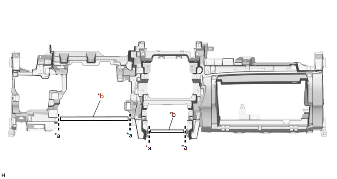
| *a | Cut-off Line | *b | Runner |
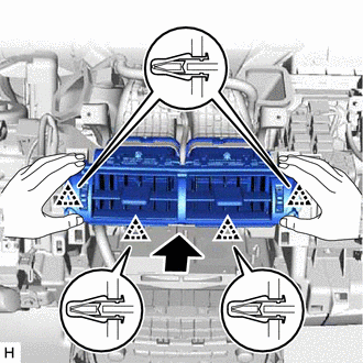
(b) Attach the 2 guides and claw to connect the hood lock control lever sub-assembly to install the lower instrument panel sub-assembly.
(c) Attach the 2 claws to connect the DLC3.
(d) Connect the connector and room temperature sensor.
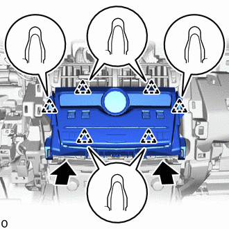
(e) Install the screw <E>.
(f) Install the 8 screws <F> or <G>.
(g) Install the 2 bolts <D>.
(h) Attach the clamps.
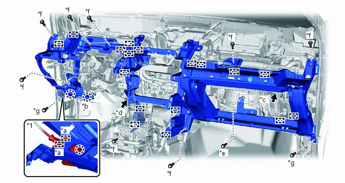
| *1 | Hood Lock Control Lever Sub-assembly | - | - |
| *a | Guide | *b | DLC3 |
| *c | Connector | *d | Room Temperature Sensor |
| *e | Screw <E> | *f | Screw <F> or <G> |
| *g | Bolt <D> | - | - |
2. INSTALL GLOVE COMPARTMENT DOOR STOPPER SUB-ASSEMBLY
(a) Attach the claw to install the glove compartment door stopper sub-assembly.
3. INSTALL NO. 1 SPEAKER ASSEMBLY WITH BOX
Click here
4. INSTALL DCM (TELEMATICS TRANSCEIVER) WITH BRACKET
Click here
5. INSTALL LOWER NO. 1 INSTRUMENT PANEL AIRBAG ASSEMBLY
Click here
6. INSTALL COWL SIDE TRIM BOARD LH
Click here
7. INSTALL COWL SIDE TRIM BOARD RH
Click here
8. INSTALL DOOR SCUFF PLATE ASSEMBLY LH
Click here
9. INSTALL DOOR SCUFF PLATE ASSEMBLY RH
Click here
10. INSTALL NO. 2 INSTRUMENT PANEL UNDER COVER SUB-ASSEMBLY
| (a) Connect the connector. |
|
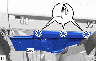
(b) Attach the guide and 3 claws to install the No. 2 instrument panel under cover sub-assembly.
11. INSTALL RADIO RECEIVER ASSEMBLY WITH BRACKET
Click here
12. INSTALL CENTER HEATER TO REGISTER DUCT
| (a) Attach the 2 claws to install the center heater to register duct. |
|
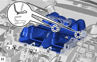
(b) Install the 2 clips <C>.
13. INSTALL CENTER INSTRUMENT PANEL REGISTER ASSEMBLY
| (a) Attach the 4 clips to install the center instrument panel register assembly. |
|
14. INSTALL AIR CONDITIONING CONTROL ASSEMBLY
| (a) Connect the connectors. |
|
(b) Attach the 6 clips to install the air conditioning control assembly.
15. INSTALL CONSOLE BOX ASSEMBLY
Click here
16. INSTALL UPPER INSTRUMENT PANEL SUB-ASSEMBLY
Click here
17. INSTALL HEADLIGHT DIMMER SWITCH ASSEMBLY
Click here
18. CONNECT CABLE TO NEGATIVE AUXILIARY BATTERY TERMINAL
19. INITIALIZATION AFTER RECONNECTING AUXILIARY BATTERY TERMINAL
Click here
HINT:
When disconnecting and reconnecting the auxiliary battery, there is an automatic learning function that completes learning when the respective system is used.
Click here
20. ENABLE AUTOAWAY/RETURN FUNCTION (for Power Tilt and Power Telescopic Steering Column)
(a) Restore the autoaway/return function setting to the previous condition by changing the customize parameter.
Click here
21. CHECK SRS WARNING LIGHT
Click here
22. INSTALL DECK FLOOR BOX LH
Click here
23. INSTALL REAR DECK FLOOR BOX
Click here
24. INSTALL NO. 3 DECK BOARD SUB-ASSEMBLY
Click here
READ NEXT:
 Components
COMPONENTS ILLUSTRATION *1 DECK BOARD ASSEMBLY *2 DECK FLOOR BOX LH *3 NO. 3 DECK BOARD SUB-ASSEMBLY *4 REAR DECK FLOOR BOX *5 NEGATIVE AUXILIARY BATTERY TERMINAL - -
Removal
REMOVAL PROCEDURE 1. REMOVE DECK BOARD ASSEMBLY (a) Remove the deck board assembly. 2. REMOVE NO. 3 DECK BOARD SUB-ASSEMBLY (a) Remove the No. 3 deck board sub-assembly.
SEE MORE:
Removal
REMOVAL CAUTION / NOTICE / HINT HINT:
Use the same procedure for the RH and LH sides.
The procedure listed below is for the LH side.
PROCEDURE 1. REMOVE REAR WHEEL Click here 2. DISCONNECT REAR SPEED SENSOR LH (a) w/ AVS: Click here (b) w/o AVS: Click here 3. DISCONNECT PARKING BRAKE W
Removal
REMOVAL PROCEDURE 1. REMOVE REAR CONSOLE END PANEL SUB-ASSEMBLY (w/ Wireless Charger) Click here 2. REMOVE CONSOLE BOX ILLUMINATION LIGHT ASSEMBLY (w/ Wireless Charger) (a) Disconnect the connector. *1 Protective Tape (b) Using a screwdriver, detach the 2 claws and remo
