Lexus NX: Disassembly
DISASSEMBLY
CAUTION / NOTICE / HINT
HINT:
- Use the same procedure for the RH and LH sides.
- The following procedure is for the LH side.
PROCEDURE
1. REMOVE CYLINDER BOOT
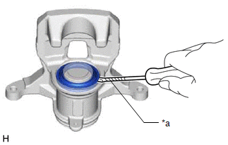
| (a) Using a screwdriver with its wrapped with protective tape, remove the piston seal from the disc brake cylinder assembly. HINT: Tape the screwdriver tip before use. NOTICE: Be careful not to damage the rear disc brake piston and rear disc brake cylinder assembly. |
|
2. REMOVE REAR DISC BRAKE PISTON
| (a) Place a piece of cloth between the rear disc brake piston and rear disc brake cylinder assembly. |
|
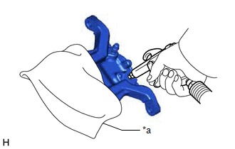
(b) Apply compressed air to remove the rear disc brake piston from the rear disc brake cylinder assembly.
CAUTION:
Do not place your fingers in front of the piston when using compressed air.
NOTICE:
Be careful not to spatter the brake fluid.
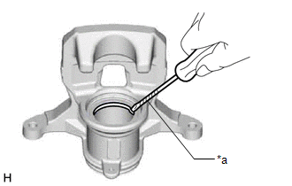
3. REMOVE PISTON SEAL
| (a) Using a screwdriver with its tip wrapped with protective tape, remove the piston seal from the rear disc brake cylinder assembly. HINT: Tape the screwdriver tip before use. NOTICE: Be careful not to damage the inner surface of the cylinder or piston seal groove. |
|
4. REMOVE REAR DISC BRAKE BLEEDER PLUG CAP
5. REMOVE REAR DISC BRAKE BLEEDER PLUG
READ NEXT:
 Inspection
INSPECTION PROCEDURE 1. CHECK BRAKE CYLINDER AND PISTON (a) Check the cylinder bore and piston for rust or scoring. If necessary, replace the disc brake cylinder and piston. 2. CHECK PAD LINING THICKN
Reassembly
REASSEMBLY CAUTION / NOTICE / HINT HINT:
Use the same procedure for the RH and LH sides.
The following procedure is for the LH side.
PROCEDURE 1. TEMPORARILY INSTALL REAR DISC BRAKE BLEEDER PL
Installation
INSTALLATION CAUTION / NOTICE / HINT HINT:
Use the same procedure for the RH and LH sides.
The following procedure is for the LH side.
NOTICE: When the brake pedal is first depressed after rep
SEE MORE:
Components
COMPONENTS ILLUSTRATION *1 FRONT AXLE HUB BOLT LH *2 FRONT DISC *3 FRONT DISC BRAKE CALIPER ASSEMBLY LH - - N*m (kgf*cm, ft.*lbf): Specified torque ● Non-reusable part
How To Proceed With Troubleshooting
CAUTION / NOTICE / HINT HINT:
Use the following procedure to troubleshoot the navigation system.
*: Use the Techstream.
PROCEDURE 1. VEHICLE BROUGHT TO WORKSHOP
NEXT 2. CUSTOMER PROBLEM ANALYSIS
When troubleshooting, confirm that the problem symptoms hav
