Lexus NX: Installation
INSTALLATION
CAUTION / NOTICE / HINT
HINT:
- Use the same procedure for the RH and LH sides.
- The following procedure is for the LH side.
NOTICE:
When the brake pedal is first depressed after replacing the brake pads or pushing back the disc brake piston, DTC C1214 may be output. As there is no malfunction, clear the DTCs.
PROCEDURE
1. INSTALL REAR DISC
| (a) Align the matchmarks of the rear disc and axle hub and install the rear disc. HINT: When replacing the disc with a new one, select the installation position where the rear disc has the smallest runout. |
|
.png)
2. INSTALL REAR DISC BRAKE BUSH DUST BOOT
| (a) Apply a light coat of lithium soap base glycol grease to the entire circumference of a new rear disc brake bush dust boot where it contacts the rear disc brake cylinder mounting, and the entire inner circumference of both of its ends. HINT: Apply at least 0.3 g (0.01 oz.) of lithium soap base glycol grease to the rear disc brake bush dust boot. |
|
(b) Install the 2 rear disc brake bush dust boots to the rear disc brake cylinder mounting.
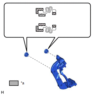
3. INSTALL REAR DISC BRAKE CYLINDER SLIDE BUSH
| (a) Apply a light coat of lithium soap base glycol grease to a new rear disc brake rear cylinder slide pin where it contacts the rear disc brake cylinder slide bush. |
|
(b) Install the rear disc brake cylinder slide bush to the rear disc brake rear cylinder slide pin.
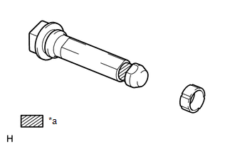
4. INSTALL REAR DISC BRAKE CYLINDER SLIDE PIN
| (a) Apply a light coat of lithium soap base glycol grease to the sliding part of the rear disc brake cylinder slide pin. |
|
(b) Install the rear No. 1 disc brake cylinder slide pin to the rear disc brake cylinder mounting LH.
(c) Push the rear No. 1 disc brake cylinder slide pin into the rear disc brake bush dust boot to align them.
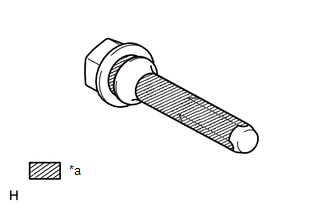
5. INSTALL REAR DISC BRAKE REAR CYLINDER SLIDE PIN
| (a) Apply a light coat of lithium soap base glycol grease to the sliding part and the seal surface of the rear disc brake rear cylinder slide pin. |
|
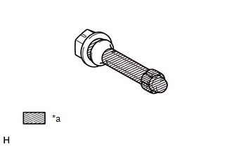
(b) Install the rear disc brake rear cylinder slide pin to the disc brake cylinder mounting LH.
(c) Push the rear disc brake rear cylinder slide pin into the rear disc brake bush dust boot to align them.
6. INSTALL REAR DISC BRAKE CYLINDER MOUNTING LH
(a) Install the rear disc brake cylinder mounting LH with the 2 bolts.
Torque:
104 N·m {1061 kgf·cm, 77 ft·lbf}
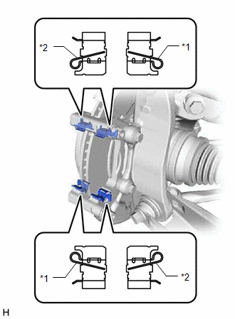
7. INSTALL REAR DISC BRAKE PAD SUPPORT PLATE
| (a) Install the 4 pad support plates to the disc brake cylinder mounting as shown in the illustration. NOTICE:
|
|
8. INSTALL REAR ANTI-SQUEAL SHIM KIT
(a) Apply disc brake grease to both surfaces of the inner rear No. 1 disc brake anti-squeal shim and only to the inner surface of the outer rear disc brake anti-squeal shim.
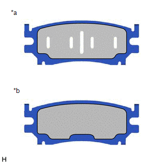
| *a | Inner Side |
| *b | Outer Side |
.png) | Disc brake grease |
NOTICE:
Make sure that disc brake grease is not applied onto the lining surface.
| (b) Install the rear No. 1 disc brake anti-squeal shim and rear No. 2 disc brake anti-squeal shim to the inner rear disc brake pad. NOTICE:
|
|
(c) Install the rear disc brake anti-squeal shim to the outer rear disc brake pad.
NOTICE:
When replacing a worn pad, the shims must be replaced together with the pads.
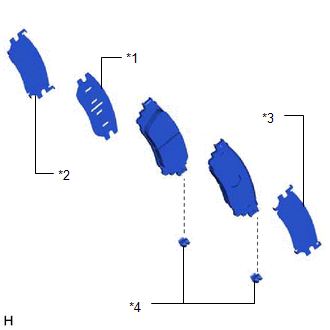
9. INSTALL REAR DISC BRAKE PAD
(a) Install the 2 new pad wear indicator plates to the rear disc brake pads.
NOTICE:
Install the pad wear indicator plates in the correct positions and directions.
(b) Install the 2 rear disc brake pads to the rear disc brake cylinder mounting LH.
NOTICE:
Make sure there is no oil or grease on the friction surface of the pads and disc.
HINT:
If the rear disc brake pad has an identification mark, be sure to confirm the installation location.
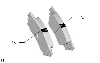
| *a | Inner Side (Purple) |
| *b | Outer Side (White) |
10. INSTALL REAR DISC BRAKE CYLINDER ASSEMBLY LH
| (a) Hold the rear disc brake cylinder slide pins and install the rear disc brake cylinder assembly to the disc brake cylinder mounting with 2 new bolts. Torque: 34.3 N·m {350 kgf·cm, 25 ft·lbf} |
|
11. INSTALL PARKING BRAKE ACTUATOR ASSEMBLY LH
(a) Apply a light coat of lithium soap base glycol grease to the new O-ring.
(b) Install the O-ring to the rear disc brake cylinder assembly LH.
(c) Using a 5 mm hexagon socket wrench, install the parking brake actuator assembly LH with the 2 bolts.
Torque:
8.4 N·m {86 kgf·cm, 74 in·lbf}
(d) Connect the connector to the parking brake actuator assembly.
12. CONNECT REAR FLEXIBLE HOSE LH
(a) Install a new gasket and connect the flexible hose with a new union bolt.
Torque:
30.4 N·m {310 kgf·cm, 22 ft·lbf}
HINT:
Install the flexible hose lock securely in the lock hole in the cylinder.
13. CONNECT CABLE TO NEGATIVE AUXILIARY BATTERY TERMINAL
(a) Connect the negative (-) auxiliary battery terminal and tighten the nut.
Torque:
5.4 N·m {55 kgf·cm, 48 in·lbf}
(b) Perform the following procedure if air bleeding is not necessary:
(1) Connect the reservoir level switch connector.
(2) Clear the DTCs.
Click here .gif)
14. INITIALIZATION AFTER RECONECTING AUXILIARY BATTERY TERMINAL
Click here
HINT:
When disconnecting and reconnecting the auxiliary battery, there is an automatic learning function that completes learning when the respective system is used.
Click here
15. INSTALL DECK FLOOR BOX LH
Click here
16. INSTALL REAR DECK FLOOR BOX
Click here
17. INSTALL NO. 3 DECK BOARD SUB-ASSEMBLY
Click here
18. BLEED BRAKE LINE
Click here
19. BLEED REAR DISC BRAKE CYLINDER ASSEMBLY
CAUTION:
If the rear disc brake cylinder assembly has been disassembled, perform air bleeding for the rear disc brake cylinder assembly.
HINT:
- Use the same procedure for the RH side and LH side.
- The following procedure is for the LH side.
- While performing air bleeding of the rear disc brake cylinder assembly, the bolts can be reused during the bleeding procedure. After air bleeding is complete, replace the bolts with new ones.
(a) Perform the procedure to enter rear disc brake pad replacement mode 5 times.
Click here
(b) Release the parking brake.
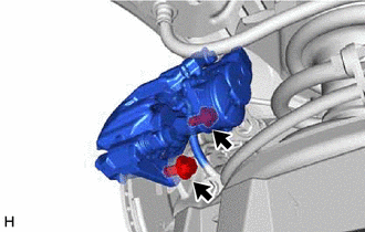
| (c) Disconnect the No. 2 parking brake wire assembly connector from the parking brake actuator assembly. |
|
.png)
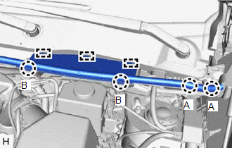
| (d) Disconnect the center No. 1 cowl top ventilator louver. (1) Slide the hood to cowl top seal and detach the 2 claws (A). (2) Detach the 2 claws (B) and 3 guides, and remove the center No. 1 cowl top ventilator louver. |
|
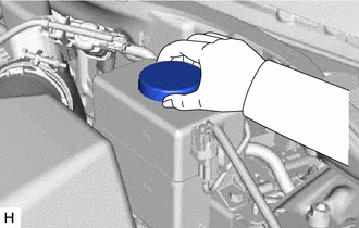
| (e) Remove the brake master cylinder reservoir filler cap assembly. |
|
(f) Add brake fluid to the brake master cylinder reservoir assembly until the brake fluid level is between the MAX and MIN lines on the brake master cylinder reservoir assembly.
NOTICE:
- Make sure that there is sufficient brake fluid in the brake master cylinder reservoir assembly.
- If brake fluid leaks onto any painted surface, immediately wash it off.
- Do not remove the filter from the brake master cylinder reservoir assembly and be sure to fill the brake master cylinder reservoir assembly with new brake fluid to avoid any potential contamination of the brake system. Contamination, for example by dirt particles or mineral oil, could lead to functional brake problems.
(g) Connect the Techstream to the DLC3 with the power switch off.
(h) Turn the power switch on (IG).
(i) Turn the Techstream on and enter the following menus: Chassis / ABS/VSC/TRAC / Utility / Air Bleeding.
Chassis > ABS/VSC/TRAC > Utility| Tester Display |
|---|
| Air Bleeding |
HINT:
Do not apply the parking brake even if instructed by the Techstream.
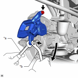
| (j) Remove the 2 bolts and separate the rear disc brake cylinder assembly with the rear disc brake cylinder mounting from the rear axle carrier sub-assembly.(*1) |
|
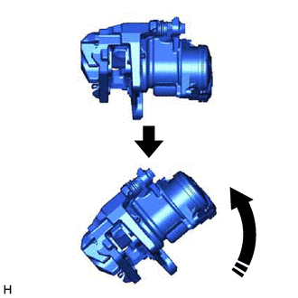
| (k) Hold the rear disc brake cylinder assembly with the rear disc brake cylinder mounting horizontally, then tilt it 45° toward the bleeder plug side as shown in the illustration.(*2) |
|
(l) Temporarily install the rear disc brake cylinder assembly with the rear disc brake cylinder mounting to the rear axle carrier sub-assembly with the 2 bolts.(*3)
(m) Using the Techstream, perform air bleeding.(*4)
(n) Follow the Techstream instructions to bleed the air from the brake fluid.(*5)
NOTICE:
Add brake fluid to keep the level between the MIN and MAX lines of the reservoir while bleeding the brake lines.
(o) Repeat steps (*1) through (*5) 3 times.
NOTICE:
If there is still air in the system after performing steps (*1) through (*5) 3 times, repeat the steps (*1) through (*5) until the air has been bled.
(p) Tighten the bleeder plug completely.
Torque:
8.3 N·m {85 kgf·cm, 73 in·lbf}
(q) Install the rear disc brake cylinder assembly with the rear disc brake cylinder mounting to the rear axle carrier sub-assembly with the 2 bolts.
Torque:
104 N·m {1061 kgf·cm, 77 ft·lbf}
(r) Connect the No. 2 parking brake wire assembly connector to the parking brake actuator assembly.
(s) Clear the DTCs.
Click here
(t) Turn the Techstream off and turn the power switch off.
(u) Disconnect the Techstream from the DLC3.
(v) Inspect for brake fluid leaks.
(w) Inspect and adjust the brake fluid level in the brake master cylinder reservoir assembly.
Click here
(x) Install the brake master cylinder reservoir filler cap assembly.
| (y) Install the center No. 1 cowl top ventilator louver. (1) Attach the 2 claws (B) and 3 guides to install the center No. 1 cowl top ventilator louver. (2) Slide the hood to cowl top seal to attach the 2 claws (A). |
|
20. INSTALL REAR WHEEL
Click here
21. RECOVERY TO NORMAL
(a) After performing repairs, operate the integration control and panel assembly (electric parking brake switch).
READ NEXT:
 Components
COMPONENTS ILLUSTRATION *1 DECK FLOOR BOX LH *2 NO. 3 DECK BOARD SUB-ASSEMBLY *3 REAR DECK FLOOR BOX *4 NEGATIVE AUXILIARY BATTERY TERMINAL N*m (kgf*cm, ft.*lbf): Specified
Removal
REMOVAL CAUTION / NOTICE / HINT HINT:
Use the same procedure for the RH and LH sides.
The following procedure is for the LH side.
NOTICE:
While the auxiliary battery is connected, even if t
SEE MORE:
Diagnosis System
DIAGNOSIS SYSTEM PARKING ASSIST MONITOR DIAGNOSIS SYSTEM (a) For panoramic view monitor system diagnosis, signals received by the parking assist ECU can be checked, and the panoramic view monitor system can be calibrated, adjusted and checked using the multi-display assembly. NOTICE: Depending on th
Reassembly
REASSEMBLY CAUTION / NOTICE / HINT HINT:
Use the same procedure for the RH and LH sides.
The procedure listed below is for the LH side.
PROCEDURE 1. INSTALL NO. 5 MOULDING TAPE (a) Clean the No. 5 moulding tape installation surface with a non-residue solvent. (b) Apply primer to the No. 5 mo
