Lexus NX: Reassembly
REASSEMBLY
CAUTION / NOTICE / HINT
HINT:
- Use the same procedure for the RH and LH sides.
- The following procedure is for the LH side.
PROCEDURE
1. TEMPORARILY INSTALL REAR DISC BRAKE BLEEDER PLUG
(a) Temporarily install the rear disc brake bleeder plug to the rear disc brake cylinder assembly.
HINT:
The rear disc brake bleeder plug will be tightened to the torque specification in the "Bleed Brake Line" procedures.
2. INSTALL REAR DISC BRAKE BLEEDER PLUG CAP
3. INSTALL PISTON SEAL
| (a) Apply a light coat of lithium soap base glycol grease to the entire inner and outer circumference of a new piston seal. |
|
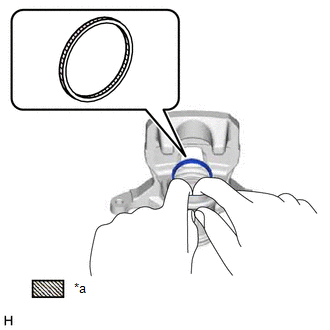
(b) Install the piston seal to the rear disc brake cylinder assembly.
NOTICE:
Make sure the piston seal is securely installed to the groove of the rear disc brake cylinder assembly.
4. INSTALL REAR DISC BRAKE PISTON
| (a) Apply a light coat of lithium soap base glycol grease to the entire inner and outer circumference of a new cylinder boot. |
|
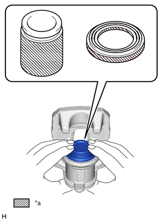
(b) Apply a light coat of lithium soap base glycol grease to the entire outer circumference of the rear disc brake piston where it contacts the rear disc brake cylinder assembly.
(c) Install the cylinder boot to the rear disc brake piston.
NOTICE:
Do not forcibly install the brake piston to the rear disc brake cylinder assembly.
(d) Install the rear disc brake piston to the rear disc brake cylinder assembly.
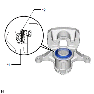
5. INSTALL CYLINDER BOOT
| (a) Install the cylinder boot to the rear disc brake cylinder assembly. NOTICE:
|
|
READ NEXT:
 Installation
INSTALLATION CAUTION / NOTICE / HINT HINT:
Use the same procedure for the RH and LH sides.
The following procedure is for the LH side.
NOTICE: When the brake pedal is first depressed after rep
Components
COMPONENTS ILLUSTRATION *1 DECK FLOOR BOX LH *2 NO. 3 DECK BOARD SUB-ASSEMBLY *3 REAR DECK FLOOR BOX *4 NEGATIVE AUXILIARY BATTERY TERMINAL N*m (kgf*cm, ft.*lbf): Specified
SEE MORE:
Barometric Pressure Sensor "A" Circuit Low (P2228-268,P2229-269)
DESCRIPTION Refer to the description for DTC P0069-273. Click here DTC No. Detection Item DTC Detection Condition Trouble Area MIL Warning Indicate P2228-268 Barometric Pressure Sensor "A" Circuit Low Open or short to ground in the atmospheric pressure sensor (1 trip detectio
Data List / Active Test
DATA LIST / ACTIVE TEST DATA LIST NOTICE: In the table below, the values listed under "Normal Condition" are reference values. Do not depend solely on these reference values when deciding whether a part is faulty or not. HINT: Using the Techstream to read the Data List allows the values or states of
