Lexus NX: Drive Motor "A" Control Module (P0A1B-198)
DESCRIPTION
The MG ECU, which is built into the inverter with converter assembly, monitors its internal operation and will store DTCs if the system is malfunctioning. If any of the following DTCs are output, replace the inverter with converter assembly.
| DTC No. | Detection Item | DTC Detection Condition | Trouble Area | MIL | Warning Indicate |
|---|---|---|---|---|---|
| P0A1B-198 | Drive Motor "A" Control Module | MG ECU internal malfunction: R/D converter NM stop error (1 trip detection logic) | Inverter with converter assembly | Comes on | Master Warning Light: Comes on |
| DTC No. | Data List |
|---|---|
| P0A1B-198 | - |
MONITOR DESCRIPTION
The MG ECU (in the inverter with converter assembly) performs many diagnostic tests to verify proper operation of internal ECU systems. In one of these tests, the MG ECU checks for an R/D (Resolver/Digital converter) malfunction involving the motor resolver. If the MG ECU detects an R/D converter error, it will conclude that there is an internal malfunction involving the motor resolver and the hybrid vehicle control ECU will illuminate the MIL and store a DTC.
MONITOR STRATEGY
| Related DTCs | P0A1B (INF 198): R/D converter NM signal stop abnormality |
| Required sensors/components | Inverter with converter assembly (MG ECU) |
| Frequency of operation | Continuous |
| Duration | TMC's intellectual property |
| MIL operation | 1 driving cycle |
| Sequence of operation | None |
TYPICAL ENABLING CONDITIONS
| The monitor will run whenever the following DTCs are not stored | TMC's intellectual property |
| Other conditions belong to TMC's intellectual property | - |
TYPICAL MALFUNCTION THRESHOLDS
| TMC's intellectual property | - |
COMPONENT OPERATING RANGE
| Hybrid vehicle control ECU | DTC P0A1B (INF 198) is not detected |
CONFIRMATION DRIVING PATTERN
- Connect the Techstream to the DLC3.
- Turn the power switch on (IG) and turn the Techstream on.
- Clear the DTCs (even if no DTCs are stored, perform the clear DTC procedure).
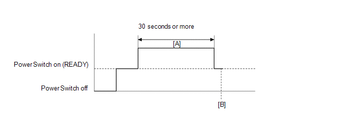
- Turn the power switch off and wait for 30 seconds or more.
- Turn the power switch on (READY).
- Drive the vehicle at 5 km/h (3 mph) or more for 30 seconds or more. [A]
- Enter the following menus: Powertrain / Hybrid Control / Trouble Codes. [B]
-
Read the current DTCs.
HINT:
- If a current DTC is output, the system is malfunctioning.
- If current DTCs are not output, check for permanent DTCs.
- Check that the permanent DTCs are cleared.
- If the permanent DTCs are not cleared, perform the universal trip, and then check for permanent DTCs again.
CAUTION / NOTICE / HINT
HINT:
If DTC P0A1B-198 is output, clear the DTCs, perform the following procedure, and check that the same DTC is not output after the repair.
- Turn the power switch on (READY).
- Drive the vehicle at 5 km/h (3 mph) or more for 30 seconds or more.
PROCEDURE
| 1. | REPLACE INVERTER WITH CONVERTER ASSEMBLY |
Click here .gif)
| NEXT | .gif) | COMPLETED |
READ NEXT:
 Drive Motor "A" Control Module (P0A1B-503)
DTC SUMMARY MALFUNCTION DESCRIPTION These DTCs indicate that an overvoltage in the inverter has occurred. The cause of this malfunction may be one of the following: Internal inverter malfunction
In
Drive Motor "A" Control Module (P0A1B-505,P0A1B-806)
DTC SUMMARY MALFUNCTION DESCRIPTION These DTCs indicate that a large current flowed in the inverter for the motor. The cause of this malfunction may be one of the following: Internal inverter malfunc
Drive Motor "A" Control Module (P0A1B-547,P0A1C-124)
DTC SUMMARY MALFUNCTION DESCRIPTION These DTCs indicate that an overvoltage in the inverter has occurred. The cause of this malfunction may be one of the following: Internal inverter malfunction
In
SEE MORE:
Problem Symptoms Table
PROBLEM SYMPTOMS TABLE HINT:
Use the table below to help determine the cause of problem symptoms. If multiple suspected areas are listed, the potential causes of the symptoms are listed in order of probability in the "Suspected Area" column of the table. Check each symptom by checking the suspect
Indicator Circuit
DESCRIPTION The LTA/LDA indicator output request signal is sent from the forward recognition camera to the combination meter assembly via CAN communication. CAUTION / NOTICE / HINT NOTICE:
When replacing the forward recognition camera, make sure to replace it with a new one. If a device that was
