Lexus NX: Drive Motor "A" Inverter Voltage Sensor Circuit Low (P0D2F-266,P0D30-267)
DESCRIPTION
The inverter contains a three-phase bridge circuit, which consists of 6 power transistors (IGBTs) each for the generator (MG1), motor (MG2) and rear motor (MGR). The inverter converts high-voltage direct current from the HV battery into three-phase alternating current for the generator (MG1), motor (MG2) and rear motor (MGR); it also converts three-phase alternating current supplied by generator (MG1), motor (MG2) and rear motor (MGR) into direct current for the HV battery. The MG ECU controls the actuation of the power transistors (IGBTs). The inverter transmits information necessary for control, such as amperage and voltage, to the MG ECU.
HINT:
The term "drive motor A" indicates the motor (MG2).
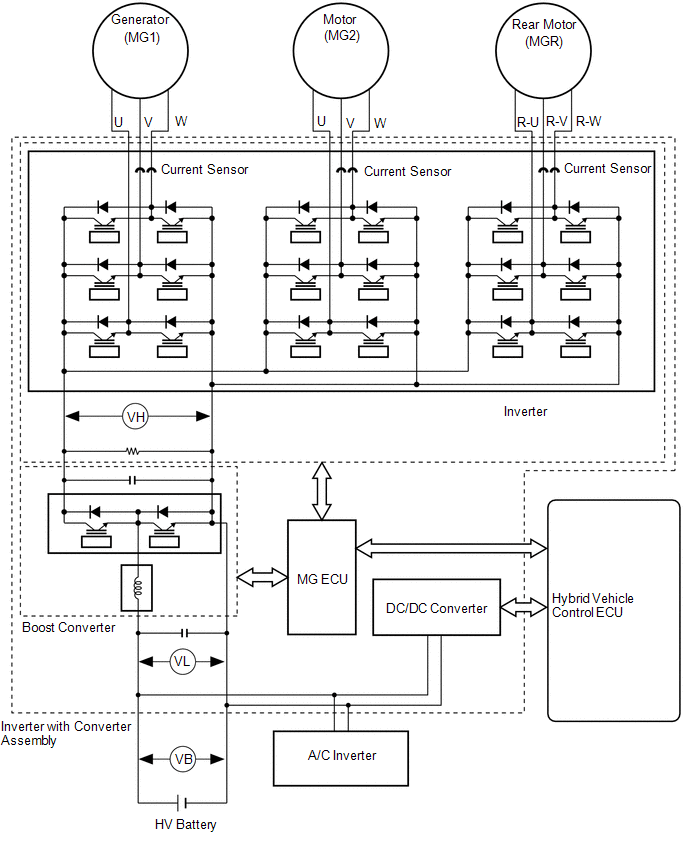
The MG ECU uses an inverter voltage sensor, which is built into the inverter, to detect boosted high voltage (VH) to allow control of the voltage boost.
The inverter voltage sensor outputs voltage that fluctuates between 0 to 5 V according to changes in VH.
The MG ECU monitors the inverter voltage sensor and detects the following malfunctions.
| DTC No. | Detection Item | DTC Detection Condition | Trouble Area | MIL | Warning Indicate |
|---|---|---|---|---|---|
| P0D2F-266 | Drive Motor "A" Inverter Voltage Sensor Circuit Low | Inverter voltage (VH) signal is stuck low: DTC stored when the VH sensor signal is excessively low. (1 trip detection logic) | Inverter with converter assembly | Comes on | Master Warning Light: Comes on |
| P0D30-267 | Drive Motor "A" Inverter Voltage Sensor Circuit High | Inverter voltage (VH) signal is stuck high: DTC stored when the VH sensor signal is excessively high. (1 trip detection logic) | Inverter with converter assembly | Comes on | Master Warning Light: Comes on |
| DTC No. | Data List |
|---|---|
| P0D2F-266 | VH-Voltage after Boosting |
| P0D30-267 |
MONITOR DESCRIPTION
The MG ECU monitors the inverter voltage (VH) sensor circuit. If the MG ECU detects an open or short in the VH sensor circuit, the hybrid vehicle control ECU will illuminate the MIL and store a DTC.
MONITOR STRATEGY
| Related DTCs | P0D2F (INF 266): VH malfunction (GND short malfunction) P0D30 (INF 267): VH malfunction (+B short and disconnection malfunction) |
| Required sensors/components | Motor inverter |
| Frequency of operation | Continuous |
| Duration | TMC's intellectual property |
| MIL operation | 1 driving cycle |
| Sequence of operation | None |
TYPICAL ENABLING CONDITIONS
| The monitor will run whenever the following DTCs are not stored | TMC's intellectual property |
| Other conditions belong to TMC's intellectual property | - |
TYPICAL MALFUNCTION THRESHOLDS
| TMC's intellectual property | - |
COMPONENT OPERATING RANGE
| Hybrid vehicle control ECU | DTC P0D2F (INF 266) is not detected DTC P0D30 (INF 267) is not detected |
CONFIRMATION DRIVING PATTERN
- Connect the Techstream to the DLC3.
- Turn the power switch on (IG) and turn the Techstream on.
- Clear the DTCs (even if no DTCs are stored, perform the clear DTC procedure).
- Turn the power switch off and wait for 30 seconds or more.
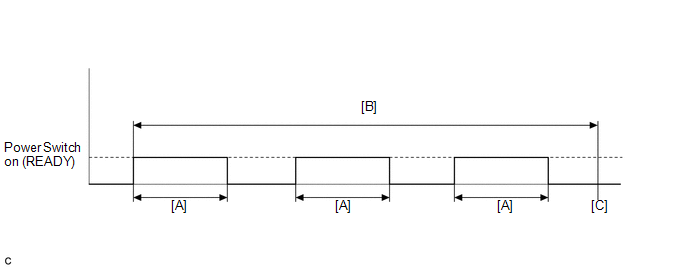
- Turn the power switch on (READY) and after 5 seconds, turn the power switch off. [A]
- Repeat [A] 3 times. [B]
- Turn the power switch on (IG) and turn the Techstream on.
- Enter the following menus: Powertrain / Hybrid Control / Trouble Codes. [C]
-
Read the current DTCs.
HINT:
- If a current DTC is output, the system is malfunctioning.
- If current DTCs are not output, perform the following steps to check for permanent DTCs.
- Check that the permanent DTCs are cleared.
- If the permanent DTCs are not cleared, perform a universal trip, and then check for permanent DTCs again.
CAUTION / NOTICE / HINT
HINT:
After the repair, clear the DTCs and perform the following procedure to check that DTCs are not output.
- Turn the power switch on (READY) and wait for 5 seconds or more.
PROCEDURE
| 1. | REPLACE INVERTER WITH CONVERTER ASSEMBLY |
Click here .gif)
HINT:
The signal line from the inverter voltage (VH) sensor is connected to the MG ECU, which is built into the inverter with converter assembly. If P0D2F-266 or P0D30-267 is output, replace the inverter with converter assembly.
| NEXT | .gif) | COMPLETED |
READ NEXT:
 Generator Phase V Current Sensor Circuit Range / Performance (P0E05-328,...,P1C72-516)
DTC SUMMARY MALFUNCTION DESCRIPTION These DTCs indicate the current sensor value is abnormal. The cause of this malfunction may be one of the following: Internal inverter malfunction
Inverter with
DC/DC Converter Voltage Sensor "A" Range / Performance (P0E32-585)
DTC SUMMARY MALFUNCTION DESCRIPTION The hybrid vehicle control ECU detects a VL sensor malfunction. The cause of this malfunction may be one of the following: Inside of inverter voltage sensor circui
DC/DC Converter Voltage Sensor "A" Low (P0E33-589,P0E34-590)
DESCRIPTION The MG ECU, which is built into the inverter with converter assembly, detects pre-boosting high voltage (VL) using the voltage sensor in the boost converter to control boosting. The MG ECU
SEE MORE:
System Description
SYSTEM DESCRIPTION ILLUMINATION CONTROL SYSTEM (Illuminated Entry System) HINT: When inspecting the following functions, make sure that the map light switch and spot light switch are in the DOOR position. (a) The illuminated entry system has the following control functions: Control Outline Li
Removal
REMOVAL CAUTION / NOTICE / HINT CAUTION: Wear protective gloves. Sharp areas on the parts may injure your hands. PROCEDURE 1. REMOVE TONNEAU COVER ASSEMBLY Click here 2. REMOVE DECK BOARD ASSEMBLY Click here 3. REMOVE BENCH TYPE REAR SEAT CUSHION ASSEMBLY (a) Lift the front end of the rear
