.gif)
- Power switch off
- Electrical key transmitter sub-assembly brought outside vehicle
- All doors closed
-
All doors locked through wireless operation
(electrical key transmitter sub-assembly brought outside detection area*)
- Driver door lock sensor touched
Lexus NX: Driver Side Door Entry Lock Function does not Operate
Lexus NX Service Manual / Vehicle Interior / Theft Deterrent / Keyless Entry / Smart Access System With Push-button Start (for Entry Function) / Driver Side Door Entry Lock Function does not Operate
DESCRIPTION
If the entry lock function does not operate for the driver door only, but the entry unlock function operates, the request code is being transmitted properly from the driver door. In this case, there may be a problem related to the lock sensor (connection between the certification ECU (smart key ECU assembly) and front door outside handle assembly (for driver door)).
WIRING DIAGRAM
.png)
CAUTION / NOTICE / HINT
NOTICE:
-
The smart access system with push-button start (for Entry Function) uses the LIN communication system and CAN communication system. Inspect the communication function by following How to Proceed with Troubleshooting. Troubleshoot the smart access system with push-button start (for Entry Function) after confirming that the communication systems are functioning properly.
Click here
.gif)
- When using the Techstream with the power switch off, connect the Techstream to the DLC3 and turn a courtesy light switch on and off at intervals of 1.5 seconds or less until communication between the Techstream and the vehicle begins. Then select the vehicle type under manual mode and enter the following menus: Body Electrical / Smart Access. While using the Techstream, periodically turn a courtesy light switch on and off at intervals of 1.5 seconds or less to maintain communication between the Techstream and the vehicle.
- Check that there are no electrical key transmitter sub-assemblies in the vehicle.
-
Before replacing the certification ECU (smart key ECU assembly), refer to smart access system with push-button start (for Entry Function) Precaution.
Click here
- After repair, confirm that no DTCs are output by performing "DTC Output Confirmation Operation".
PROCEDURE
| 1. | CHECK POWER DOOR LOCK CONTROL SYSTEM |
(a) When the door control switch on the multiplex network master switch assembly is operated, check that the doors unlock and lock according to the switch operation.
Click here
OK:
Door locks operate normally.
| NG | .gif) | GO TO POWER DOOR LOCK CONTROL SYSTEM |
|
| 2. | READ VALUE USING TECHSTREAM (D-DOOR TRIGGER SWITCH) |
(a) Connect the Techstream to the DLC3.
(b) Turn the power switch on (IG).
(c) Turn the Techstream on.
(d) Enter the following menus: Body Electrical / Smart Access / Data List.
(e) Read the Data List according to the display on the Techstream.
Body Electrical > Smart Access > Data List| Tester Display | Measurement Item | Range | Normal Condition | Diagnostic Note |
|---|---|---|---|---|
| D-Door Trigger Switch | Driver door touch sensor (lock sensor) | ON or OFF | ON: Driver door touch sensor (lock sensor) touched OFF: Driver door touch sensor (lock sensor) not touched |
|
| Tester Display |
|---|
| D-Door Trigger Switch |
HINT:
When checking the operation of the entry lock function several times, it can be operated up to 2 times consecutively. To operate the function 3 times or more consecutively, the doors need to be unlocked once. However, this is only for the entry lock function, other door lock operations, such as a wireless door lock operation can be performed consecutively.
OK:
The Techstream display changes correctly in response to the operation of the front door outside handle assembly (for driver door).
| OK | | REPLACE CERTIFICATION ECU (SMART KEY ECU ASSEMBLY) |
|
| 3. | CHECK HARNESS AND CONNECTOR (CERTIFICATION ECU (SMART KEY ECU ASSEMBLY) - FRONT DOOR OUTSIDE HANDLE ASSEMBLY (FOR DRIVER DOOR)) |
(a) Disconnect the I53 certification ECU (smart key ECU assembly) connector.
(b) Disconnect the M4 front door outside handle assembly (for driver door) connector.
(c) Measure the resistance according to the value(s) in the table below.
Standard Resistance:
| Tester Connection | Condition | Specified Condition |
|---|---|---|
| I53-4 (CLG1) - M4-4 (ANT1) | Always | Below 1 Ω |
| I53-3 (CG1B) - M4-5 (ANT2) | Always | Below 1 Ω |
| I53-4 (CLG1) or M4-4 (ANT1) - Body ground | Always | 10 kΩ or higher |
| I53-3 (CG1B) or M4-5 (ANT2) - Body ground | Always | 10 kΩ or higher |
(d) Reconnect the M4 front door outside handle assembly (for driver door) connector.
(e) Reconnect the I53 certification ECU (smart key ECU assembly) connector.
| NG | | REPAIR OR REPLACE HARNESS OR CONNECTOR |
|
| 4. | CHECK FRONT DOOR OUTSIDE HANDLE ASSEMBLY (FOR DRIVER DOOR) (INPUT TO DRIVER DOOR LOCK SENSOR) |
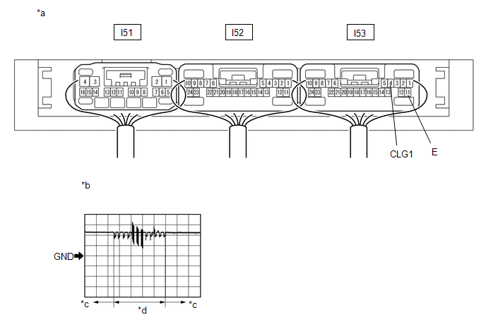
| *a | Component with harness connected (Certification ECU (Smart Key ECU Assembly)) | *b | Waveform 1 |
| *c | Lock sensor not touched | *d | Lock sensor touched |
(a) Using an oscilloscope, check the waveform.
OK:
| Tester Connection | Condition | Tool Setting | Specified Condition |
|---|---|---|---|
| I53-4 (CLG1) - I53-11 (E) | Procedure: | 5 V/DIV., 40 ms/DIV. | Pulse generation (See waveform 1) |
*: For details about the entry function detection area, refer to Operation Check.
Click here
| OK | | REPLACE CERTIFICATION ECU (SMART KEY ECU ASSEMBLY) |
| NG | | REPLACE FRONT DOOR OUTSIDE HANDLE ASSEMBLY (FOR DRIVER DOOR) |
READ NEXT:
 Front Passenger Side Door Entry Lock Function does not Operate
DESCRIPTION If the entry lock function does not operate for the front passenger door only, but the entry unlock function operates, the request code is being transmitted properly from the for passenger
Rear Door LH Entry Lock Function does not Operate
DESCRIPTION If the entry lock function does not operate for the rear door LH only, but the entry unlock function operates, the request code is being transmitted properly from the rear door LH. In this
Rear Door RH Entry Lock Function does not Operate
DESCRIPTION If the entry lock function does not operate for the rear door RH only, but the entry unlock function operates, the request code is being transmitted properly from the for rear door RH. In
SEE MORE:
Inspection
INSPECTION PROCEDURE 1. INSPECT POWER BACK DOOR SENSOR ASSEMBLY LH (a) Measure the resistance according to the value(s) in the table below. Standard Resistance: Tester Connection Condition Specified Condition 1 (OSL) - 2 (OSLE) Not pressed 950 to 1050 Ω 1 (OSL) - 2 (OSLE) P
Startability Malfunction (P1604)
DESCRIPTION If the engine does not start or it takes a long time for the engine to start, despite the ECM receiving the engine start request signal from the hybrid vehicle control ECU via CAN communication, this DTC will be stored. Read freeze frame data using the Techstream. The ECM records vehicle
© 2016-2026 Copyright www.lexunx.com
