Lexus NX: Inspection
INSPECTION
PROCEDURE
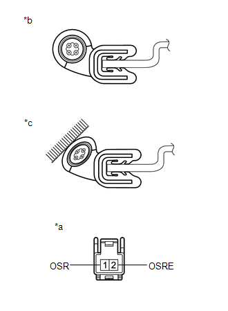
1. INSPECT POWER BACK DOOR SENSOR ASSEMBLY LH
| (a) Measure the resistance according to the value(s) in the table below. Standard Resistance:
If the result is not as specified, replace the power back door sensor assembly LH. |
|

2. INSPECT POWER BACK DOOR SENSOR ASSEMBLY RH
| (a) Measure the resistance according to the value(s) in the table below. Standard Resistance:
If the result is not as specified, replace the power back door sensor assembly RH. |
|
READ NEXT:
 Installation
INSTALLATION CAUTION / NOTICE / HINT HINT:
Use the same procedure for the RH and LH sides.
The procedure listed below is for the LH side.
PROCEDURE 1. INSTALL POWER BACK DOOR SENSOR ASSEMBLY L
Components
COMPONENTS ILLUSTRATION *A w/ Woofer *B w/o Woofer *1 BACK DOOR CENTER GARNISH *2 BACK DOOR LOCK COVER *3 BACK DOOR SIDE GARNISH LH *4 BACK DOOR SIDE GARNISH RH *5
SEE MORE:
Components
COMPONENTS ILLUSTRATION *1 COWL SIDE TRIM BOARD LH *2 DOOR SCUFF PLATE ASSEMBLY LH *3 FRONT FLOOR CARPET ASSEMBLY *4 NO. 4 DASH PANEL INSULATOR PAD (FRONT FLOOR FOOTREST)
On-vehicle Inspection
ON-VEHICLE INSPECTION CAUTION / NOTICE / HINT CAUTION: Be sure to follow the correct removal and installation procedures of the lower No. 1 instrument panel airbag assembly. PROCEDURE 1. INSPECT LOWER NO. 1 INSTRUMENT PANEL AIRBAG ASSEMBLY (for Vehicle not Involved in Collision) (a) Perform a diagno
