.gif)
- Power switch off
- Electrical key transmitter sub-assembly brought outside vehicle
- All doors closed
-
All doors locked through wireless operation
(electrical key transmitter sub-assembly brought outside detection area*)
- Rear door RH lock sensor touched
Lexus NX: Rear Door RH Entry Lock Function does not Operate
Lexus NX Service Manual / Vehicle Interior / Theft Deterrent / Keyless Entry / Smart Access System With Push-button Start (for Entry Function) / Rear Door RH Entry Lock Function does not Operate
DESCRIPTION
If the entry lock function does not operate for the rear door RH only, but the entry unlock function operates, the request code is being transmitted properly from the for rear door RH. In this case, there may be a problem related to the lock sensor (connection between the certification ECU (smart key ECU assembly) and rear door outside handle assembly RH).
WIRING DIAGRAM
.png)
CAUTION / NOTICE / HINT
NOTICE:
-
The smart access system with push-button start (for Entry Function) uses the LIN communication system and CAN communication system. Inspect the communication function by following How to Proceed with Troubleshooting. Troubleshoot the smart access system with push-button start (for Entry Function) after confirming that the communication systems are functioning properly.
Click here
.gif)
- When using the Techstream with the power switch off, connect the Techstream to the DLC3 and turn a courtesy light switch on and off at intervals of 1.5 seconds or less until communication between the Techstream and the vehicle begins. Then select the vehicle type under manual mode and enter the following menus: Body Electrical / Smart Access. While using the Techstream, periodically turn a courtesy light switch on and off at intervals of 1.5 seconds or less to maintain communication between the Techstream and the vehicle.
- Check that there are no electrical key transmitter sub-assemblies in the vehicle.
-
Before replacing the certification ECU (smart key ECU assembly), refer to smart access system with push-button start (for Entry Function) Precaution.
Click here
- After repair, confirm that no DTCs are output by performing "DTC Output Confirmation Operation".
PROCEDURE
| 1. | CHECK POWER DOOR LOCK CONTROL SYSTEM |
(a) When the door control switch on the multiplex network master switch assembly is operated, check that the doors unlock and lock according to the switch operation.
Click here
OK:
Door locks operate normally.
| NG | .gif) | GO TO POWER DOOR LOCK CONTROL SYSTEM |
|
| 2. | READ VALUE USING TECHSTREAM (PR-DOOR TRIGGER SWITCH) |
(a) Connect the Techstream to the DLC3.
(b) Turn the power switch on (IG).
(c) Turn the Techstream on.
(d) Enter the following menus: Body Electrical / Smart Access / Data List.
(e) Read the Data List according to the display on the Techstream.
Body Electrical > Smart Access > Data List| Tester Display | Measurement Item | Range | Normal Condition | Diagnostic Note |
|---|---|---|---|---|
| Pr-Door Trigger Switch | Rear door RH touch sensor (lock sensor) | ON or OFF | ON: Rear door RH touch sensor (lock sensor) touched OFF: Rear door RH touch sensor (lock sensor) not touched |
|
| Tester Display |
|---|
| Pr-Door Touch Sensor |
HINT:
When checking the operation of the entry lock function several times, it can be operated up to 2 times consecutively. To operate the function 3 times or more consecutively, the doors need to be unlocked once. However, this is only for the entry lock function, other door lock operations, such as a wireless door lock operation can be performed consecutively.
OK:
The Techstream display changes correctly in response to the operation of the rear door outside handle assembly RH.
| OK | | REPLACE CERTIFICATION ECU (SMART KEY ECU ASSEMBLY) |
|
| 3. | CHECK HARNESS AND CONNECTOR (CERTIFICATION ECU (SMART KEY ECU ASSEMBLY) - REAR DOOR OUTSIDE HANDLE ASSEMBLY RH) |
(a) Disconnect the I52 certification ECU (smart key ECU assembly) connector.
(b) Disconnect the N4 rear door outside handle assembly RH connector.
(c) Measure the resistance according to the value(s) in the table below.
Standard Resistance:
| Tester Connection | Condition | Specified Condition |
|---|---|---|
| I52-10 (CLG4) - N4-4 (ANT1) | Always | Below 1 Ω |
| I52-9 (CG4B) - N4-5 (ANT2) | Always | Below 1 Ω |
| I52-10 (CLG4) or N4-4 (ANT1) - Body ground | Always | 10 kΩ or higher |
| I52-9 (CG4B) or N4-5 (ANT2) - Body ground | Always | 10 kΩ or higher |
(d) Reconnect the N4 rear door outside handle assembly RH connector.
(e) Reconnect the I52 certification ECU (smart key ECU assembly) connector.
| NG | | REPAIR OR REPLACE HARNESS OR CONNECTOR |
|
| 4. | CHECK REAR DOOR OUTSIDE HANDLE ASSEMBLY RH (INPUT TO REAR DOOR RH LOCK SENSOR) |
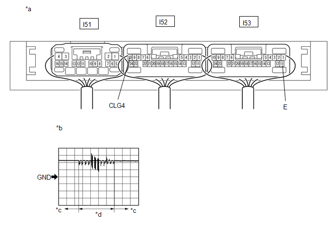
| *a | Component with harness connected (Certification ECU (Smart Key ECU Assembly)) | *b | Waveform 1 |
| *c | Lock sensor not touched | *d | Lock sensor touched |
(a) Using an oscilloscope, check the waveform.
OK:
| Tester Connection | Condition | Tool Setting | Specified Condition |
|---|---|---|---|
| I52-10 (CLG4) - I53-11 (E) | Procedure: | 5 V/DIV., 40 ms/DIV. | Pulse generation (See waveform 1) |
*: For details about the entry function detection area, refer to Operation Check.
Click here
| OK | | REPLACE CERTIFICATION ECU (SMART KEY ECU ASSEMBLY) |
| NG | | REPLACE REAR DOOR OUTSIDE HANDLE ASSEMBLY RH |
READ NEXT:
 Room Oscillator does not Recognize Key
DESCRIPTION If code verification cannot be performed in the vehicle interior, there may be problems with the communication between the vehicle (No. 1 indoor electrical key antenna assembly (front floo
Entry Interior Alarm does not Sound
DESCRIPTION The smart access system with push-button start (for Entry Function) uses the buzzer in the combination meter assembly (meter ECU) to perform various vehicle interior warnings. When the con
Back Door Entry Unlock Function does not Operate
DESCRIPTION If the entry unlock function does not operate for the back door only, but the entry lock function operates, the request code is being transmitted properly from the back door. In this case,
SEE MORE:
Components
COMPONENTS ILLUSTRATION *1 RAIN SENSOR *2 RAIN SENSOR COVER *3 RAIN SENSOR TAPE - -
Steering Wheel does not Heat Up When Heated Steering Wheel Switch is Pressed
DESCRIPTION Click here WIRING DIAGRAM Click here CAUTION / NOTICE / HINT HINT:
Inspect the fuses for circuits related to this system before performing the following inspection procedure.
The steering wheel heater unit is built into the steering wheel assembly which cannot be disassembled. T
© 2016-2026 Copyright www.lexunx.com
