
Lexus NX: Components
COMPONENTS
ILLUSTRATION
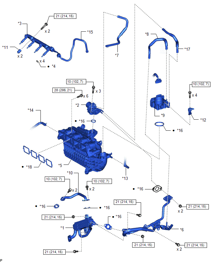
| *1 | EGR COOLER ASSEMBLY | *2 | EGR VALVE ASSEMBLY |
| *3 | FUEL DELIVERY PIPE | *4 | INJECTOR VIBRATION INSULATOR |
| *5 | INTAKE MANIFOLD | *6 | NO. 1 EGR PIPE |
| *7 | NO. 1 WATER BY-PASS HOSE | *8 | NO. 3 WATER BY-PASS HOSE |
| *9 | THROTTLE WITH MOTOR BODY ASSEMBLY | *10 | WATER BY-PASS PIPE |
| *11 | NO. 1 FUEL DELIVERY SPACER | *12 | FUEL HOSE BRACKET |
| *13 | PURGE LINE HOSE | *14 | NO. 2 PCV HOSE |
| *15 | FUEL TUBE SUB-ASSEMBLY | *16 | GASKET |
| *17 | NO. 2 WATER BY-PASS HOSE | *18 | NO. 1 INTAKE MANIFOLD TO HEAD GASKET |
.png) | N*m (kgf*cm, ft.*lbf): Specified torque | ● | Non-reusable part |
ILLUSTRATION
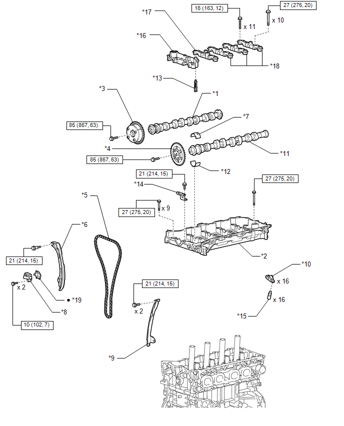
| *1 | CAMSHAFT | *2 | CAMSHAFT HOUSING SUB-ASSEMBLY |
| *3 | CAMSHAFT TIMING GEAR ASSEMBLY | *4 | CAMSHAFT TIMING SPROCKET |
| *5 | CHAIN SUB-ASSEMBLY | *6 | CHAIN TENSIONER SLIPPER |
| *7 | NO. 1 CAMSHAFT BEARING | *8 | NO. 1 CHAIN TENSIONER ASSEMBLY |
| *9 | NO. 1 CHAIN VIBRATION DAMPER | *10 | NO. 1 VALVE ROCKER ARM SUB-ASSEMBLY |
| *11 | NO. 2 CAMSHAFT | *12 | NO. 2 CAMSHAFT BEARING |
| *13 | OIL CONTROL VALVE FILTER | *14 | TIMING CHAIN GUIDE |
| *15 | VALVE LASH ADJUSTER ASSEMBLY | *16 | NO. 1 CAMSHAFT BEARING CAP |
| *17 | NO. 2 CAMSHAFT BEARING CAP | *18 | NO. 3 CAMSHAFT BEARING CAP |
| *19 | GASKET | - | - |
| | N*m (kgf*cm, ft.*lbf): Specified torque | ● | Non-reusable part |
ILLUSTRATION
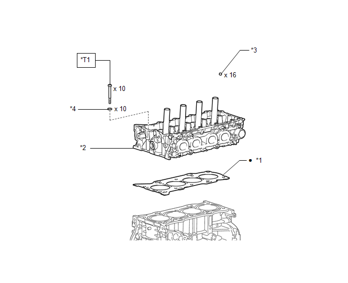
| *1 | CYLINDER HEAD GASKET | *2 | CYLINDER HEAD SUB-ASSEMBLY |
| *3 | VALVE STEM CAP | *4 | PLATE WASHER |
| | N*m (kgf*cm, ft.*lbf): Specified torque | ● | Non-reusable part |
| *T1 | 1st: 36 N*m (367 kgf*cm, 27 ft.*lbf) 2nd: 36 N*m (367 kgf*cm, 27 ft.*lbf) 3rd: Turn 90° 4th: Turn 90° | - | - |
READ NEXT:
 Removal
REMOVAL PROCEDURE 1. REMOVE TIMING CHAIN COVER ASSEMBLY Click here 2. REMOVE EXHAUST MANIFOLD CONVERTER SUB-ASSEMBLY Click here 3. REMOVE THROTTLE WITH MOTOR BODY ASSEMBLY Click here 4. REMOVE W
Installation
INSTALLATION CAUTION / NOTICE / HINT HINT: Perform "Inspection After Repairs" after replacing the cylinder head sub-assembly. Click here PROCEDURE 1. INSTALL CYLINDER HEAD GASKET (a) Clean the cylin
Drive Belt
ComponentsCOMPONENTS ILLUSTRATION *1 FAN AND GENERATOR V BELT *2 REAR ENGINE UNDER COVER RH On-vehicle InspectionON-VEHICLE INSPECTION PROCEDURE 1. INSPECT FAN AND GENERATOR V BELT (
SEE MORE:
Software Incompatibility with Body Control Module Not Programmed (U032251)
DESCRIPTION The forward recognition camera receives vehicle specification information from the main body ECU (multiplex network body ECU) via the CAN communication line. When the forward recognition camera is unable to determine the vehicle information from the vehicle specification information sent
Reassembly
REASSEMBLY PROCEDURE 1. INSTALL NO. 2 MOULDING TAPE HINT:
When installing the No. 2 moulding tape, heat the front bumper cover and No. 2 moulding tape using a heat light.
Use the same procedure described for the other side.
Standard: Item Temperature Front Bumper Cover 20 to 30°
