Lexus NX: ECU Power Source Circuit
DESCRIPTION
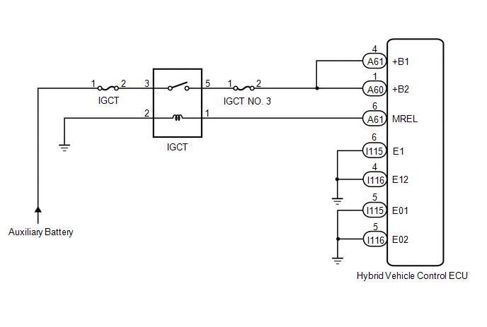
If the power switch is on (IG), the hybrid vehicle control ECU applies current to the MREL terminal to turn the IGCT relay on. This supplies power to the +B1 and +B2 terminals.
WIRING DIAGRAM
Refer to the wiring diagram for DTC P0A08-264.
Click here .gif)
PROCEDURE
| 1. | CHECK HYBRID VEHICLE CONTROL ECU (+B1, +B2 VOLTAGE) |
(a) Turn the power switch on (IG).
| (b) Measure the voltage according to the value(s) in the table below. Standard Voltage:
|
|
(c) Turn the power switch off.
| NG | .gif) | GO TO STEP 3 |
|
.gif)
| 2. | CHECK HARNESS AND CONNECTOR (HYBRID VEHICLE CONTROL ECU - BODY GROUND) |
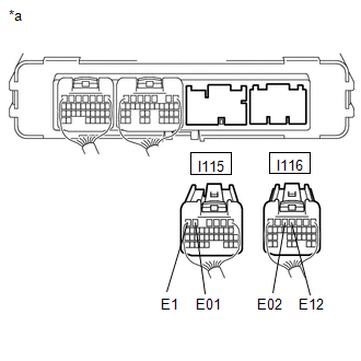
(a) Disconnect the I115 and I116 hybrid vehicle control ECU connectors.
| (b) Measure the resistance according to the value(s) in the table below. Standard Resistance:
|
|
(c) Reconnect the I115 and I116 hybrid vehicle control ECU connectors.
| OK | | GO TO PROBLEM SYMPTOMS TABLE |
| NG | | REPAIR OR REPLACE HARNESS OR CONNECTOR |
| 3. | CHECK HYBRID VEHICLE CONTROL ECU (MREL VOLTAGE) |
(a) Turn the power switch on (IG).
| (b) Measure the voltage according to the value(s) in the table below. Standard Voltage:
|
|
(c) Turn the power switch off.
| NG | | REPLACE HYBRID VEHICLE CONTROL ECU |
|
| 4. | CHECK FUSE (IGCT NO. 3) |
| (a) Remove the IGCT NO. 3 fuse from the No. 1 engine room relay block. |
|
(b) Measure the resistance according to the value(s) in the table below.
Standard Resistance:
| Tester Connection | Condition | Specified Condition |
|---|---|---|
| IGCT NO. 3 fuse terminals | Always | Below 1 Ω |
(c) Install the IGCT NO. 3 fuse.
| NG | | GO TO STEP 12 |
|
| 5. | CHECK FUSE (IGCT) |
| (a) Remove the IGCT fuse from the No. 1 engine room relay block. |
|
(b) Measure the resistance according to the value(s) in the table below.
Standard Resistance:
| Tester Connection | Condition | Specified Condition |
|---|---|---|
| IGCT fuse terminals | Always | Below 1 Ω |
(c) Install the IGCT fuse.
| NG | | GO TO STEP 13 |
|
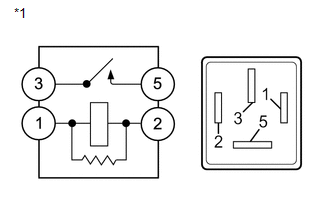
| 6. | INSPECT RELAY (IGCT) |
(a) Remove the IGCT relay from the No. 1 engine room relay block.
| (b) Measure the resistance according to the value(s) in the table below. Standard Resistance:
|
|
(c) Install the IGCT relay.
| NG | | REPLACE RELAY (IGCT) |
|
| 7. | CHECK HARNESS AND CONNECTOR (NO. 1 ENGINE ROOM RELAY BLOCK - HYBRID VEHICLE CONTROL ECU) |
| (a) Remove the IGCT NO. 3 fuse from the No. 1 engine room relay block. |
|
(b) Disconnect the A60 and A61 hybrid vehicle control ECU connectors.
(c) Measure the resistance according to the value(s) in the table below.
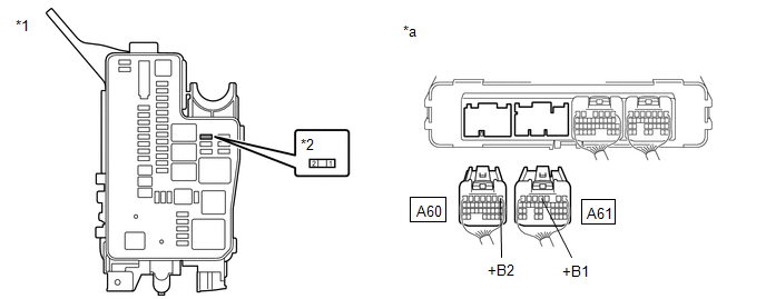
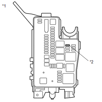
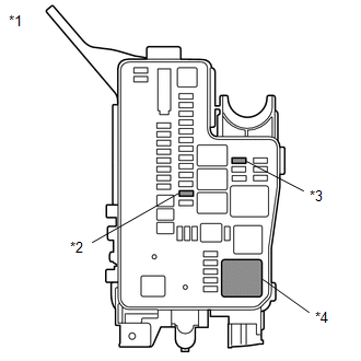
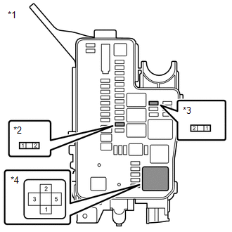
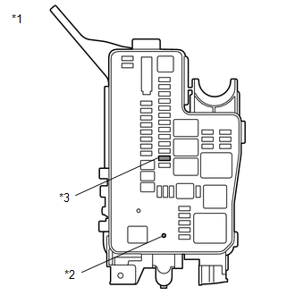
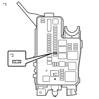
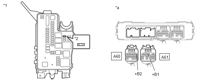
| *1 | No. 1 Engine Room Relay Block | *2 | IGCT NO. 3 Fuse |
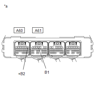
| *a | Rear view of wire harness connector (to Hybrid Vehicle Control ECU) | - | - |
Standard Resistance:
| Tester Connection | Condition | Specified Condition |
|---|---|---|
| A61-4 (+B1) - 2 (IGCT NO. 3 fuse) | Always | Below 1 Ω |
| A60-1 (+B2) - 2 (IGCT NO. 3 fuse) | Always | Below 1 Ω |
(d) Reconnect the A60 and A61 hybrid vehicle control ECU connectors.
(e) Install the IGCT NO. 3 fuse.
| NG | | REPAIR OR REPLACE HARNESS OR CONNECTOR |
|
| 8. | CHECK HARNESS AND CONNECTOR (NO. 1 ENGINE ROOM RELAY BLOCK) |
| (a) Remove the IGCT fuse, IGCT NO. 3 fuse and IGCT relay from the No. 1 engine room relay block. |
|
| (b) Measure the resistance according to the value(s) in the table below. Standard Resistance:
|
|
(c) Install the IGCT fuse, IGCT NO. 3 fuse and IGCT relay.
| NG | | REPAIR OR REPLACE HARNESS OR CONNECTOR |
|
| 9. | CHECK HARNESS AND CONNECTOR (HYBRID VEHICLE CONTROL ECU - NO. 1 ENGINE ROOM RELAY BLOCK) |
(a) Disconnect the A61 hybrid vehicle control ECU connector.
(b) Remove the IGCT relay from the No. 1 engine room relay block.
(c) Measure the resistance according to the value(s) in the table below.
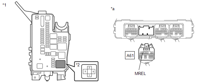
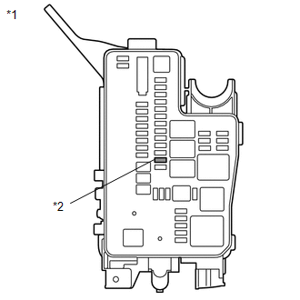
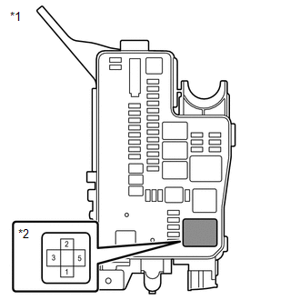
| *1 | No. 1 Engine Room Relay Block | *2 | IGCT Relay |
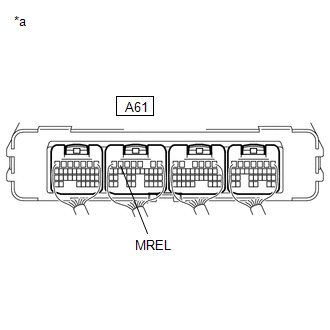
| *a | Rear view of wire harness connector (to Hybrid Vehicle Control ECU) | - | - |
Standard Resistance:
| Tester Connection | Condition | Specified Condition |
|---|---|---|
| A61-6 (MREL) - 1 (IGCT relay) | Always | Below 1 Ω |
| A61-6 (MREL) or 1 (IGCT relay) - Body ground and other terminals | Always | 10 kΩ or higher |
(d) Install the IGCT relay.
(e) Reconnect the A61 hybrid vehicle control ECU connector.
| NG | | REPAIR OR REPLACE HARNESS OR CONNECTOR |
|
| 10. | CHECK HARNESS AND CONNECTOR (NO. 1 ENGINE ROOM RELAY BLOCK - BODY GROUND) |
(a) Remove the IGCT relay from the No. 1 engine room relay block.
| (b) Measure the resistance according to the value(s) in the table below. Standard Resistance:
|
|
(c) Install the IGCT relay.
| NG | | REPAIR OR REPLACE HARNESS OR CONNECTOR |
|
| 11. | CHECK HARNESS AND CONNECTOR (NO. 1 ENGINE ROOM RELAY BLOCK) |
| (a) Disconnect the No. 2 engine room wire from the AMD terminal (No. 1 engine room relay block side). |
|
(b) Remove the IGCT fuse from the No. 1 engine room relay block.
| (c) Measure the resistance according to the value(s) in the table below. Standard Resistance:
|
|
(d) Install the IGCT fuse.
(e) Reconnect the No. 2 engine room wire.
| OK | | CHECK FOR INTERMITTENT PROBLEMS |
| NG | | GO TO STEP 14 |
| 12. | CHECK HARNESS AND CONNECTOR (NO. 1 ENGINE ROOM RELAY BLOCK - HYBRID VEHICLE CONTROL ECU) |
| (a) Remove the IGCT NO. 3 fuse from the No. 1 engine room relay block. |
|
(b) Disconnect the A60 and A61 hybrid vehicle control ECU connectors.
(c) Measure the resistance according to the value(s) in the table below.
| *1 | No. 1 Engine Room Relay Block | *2 | IGCT NO. 3 Fuse |
| *a | Rear view of wire harness connector (to Hybrid Vehicle Control ECU) | - | - |
Standard Resistance:
| Tester Connection | Condition | Specified Condition |
|---|---|---|
| A61-4 (+B1) or 2 (IGCT NO. 3 fuse) - Body ground and other terminals | Always | 10 kΩ or higher |
| A60-1 (+B2) or 2 (IGCT NO. 3 fuse) - Body ground and other terminals | Always | 10 kΩ or higher |
(d) Reconnect the A60 and A61 hybrid vehicle control ECU connectors.
(e) Install the IGCT NO. 3 fuse.
| OK | | REPLACE FUSE (IGCT NO. 3) |
| NG | | GO TO STEP 15 |
| 13. | CHECK HARNESS AND CONNECTOR (NO. 1 ENGINE ROOM RELAY BLOCK) |
| (a) Disconnect the IGCT fuse, IGCT NO. 3 fuse and IGCT relay from the No. 1 engine room relay block. |
|
| (b) Measure the resistance according to the value(s) in the table below. Standard Resistance:
|
|
(c) Install the IGCT fuse, IGCT NO. 3 fuse and IGCT relay.
| OK | | REPLACE RELAY (IGCT) |
| NG | | GO TO STEP 16 |
| 14. | CHECK FUSE (DC/DC) |
Click here
| OK | | REPAIR OR REPLACE HARNESS OR CONNECTOR |
| NG | | REPLACE FUSE (DC/DC) |
| 15. | REPAIR OR REPLACE HARNESS OR CONNECTOR |
| NEXT | | REPLACE FUSE (IGCT NO. 3) |
| 16. | REPAIR OR REPLACE HARNESS OR CONNECTOR |
| NEXT | | REPLACE FUSE (IGCT) |
READ NEXT:
 Motor Resolver Circuit
DESCRIPTION The cause of this malfunction may be the motor resolver. Check the motor resolver internal resistance and the connection condition from the inverter to the resolver. Related Parts Check
Motor High-voltage Circuit
DESCRIPTION The cause of the malfunction may be the high-voltage circuit of the motor. Check the motor internal resistance and the connection condition of the high-voltage line between the inverter an
Generator Resolver Circuit
DESCRIPTION The cause of this malfunction may be the generator resolver. Check the generator resolver internal resistance and connection condition from the inverter to the resolver. Related Parts Chec
SEE MORE:
Removal
REMOVAL PROCEDURE 1. REMOVE BACK DOOR CENTER GARNISH Click here 2. REMOVE REAR SPOILER ASSEMBLY (a) Remove the 2 hole plugs. Nut Bolt Connector (b) Remove the 4 nuts. (c) Remove the 2 bolts. (d) Disconnect the 2 connectors. (e) Put protective tape around the rear spoile
ECU Malfunction (C1611)
DESCRIPTION If the clearance warning ECU assembly detects an internal malfunction during self-diagnosis, DTC C1611 is stored. DTC No. Detection Item DTC Detection Condition Trouble Area C1611 ECU Malfunction
Sub-CPU abnormal signal
Mirror check abnormal
Clearance warning E
