Lexus NX: Removal
REMOVAL
PROCEDURE
1. PRECAUTION
NOTICE:
After turning the power switch is turned off, there may be a waiting time before disconnecting the auxiliary negative (-) battery terminal.
Click here .gif)
2. CUSTOMIZE POWER TILT AND POWER TELESCOPIC STEERING COLUMN SYSTEM
(a) Disable the auto tilt away function by changing the customize parameter.
Click here
NOTICE:
Record the current customize parameter setting (whether the auto tilt away function is enabled or disabled) in order to restore the current setting after finishing the operation.
HINT:
Performing the above operation causes the auto tilt away function to be disabled when the power switch is turned off.
(b) Turn the power switch on (IG). Operate the tilt and telescopic switch to fully extend and lower the steering column assembly.
3. REMOVE NO. 3 DECK BOARD SUB-ASSEMBLY
Click here
4. REMOVE REAR DECK FLOOR BOX
Click here
5. REMOVE DECK FLOOR BOX LH
Click here
6. DISCONNECT CABLE FROM NEGATIVE AUXILIARY BATTERY TERMINAL
7. REMOVE LOWER STEERING COLUMN COVER
Click here
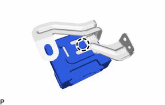
8. REMOVE MULTIPLEX TILT AND TELESCOPIC ECU
| (a) Disconnect the harness clamp and connector. |
|
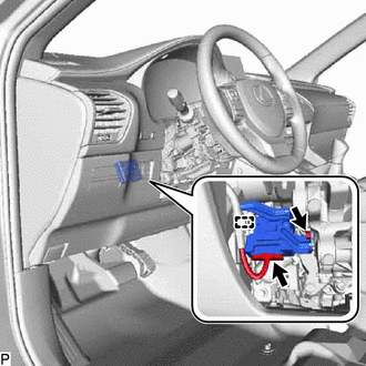
(b) Remove the bolt and multiplex tilt and telescopic ECU from the electric power steering column sub-assembly.
| (c) Detach the claw and remove the multiplex tilt and telescopic ECU from the bracket. |
|
READ NEXT:
 Precaution
PRECAUTION PRECAUTION FOR DISCONNECTING CABLE FROM NEGATIVE AUXILIARY BATTERY TERMINAL NOTICE:
After turning the power switch off, waiting time may be required before disconnecting the cable from t
Parts Location
PARTS LOCATION ILLUSTRATION *A w/ Seat Memory - *1 FRONT POWER SEAT SWITCH LH *2 SEAT MEMORY SWITCH *3 TILT AND TELESCOPIC SWITCH *4 ELECTRIC POWER STEERING COLUMN S
SEE MORE:
Removal
REMOVAL PROCEDURE 1. REMOVE CONSOLE BOX ASSEMBLY Click here 2. REMOVE DOOR SCUFF PLATE ASSEMBLY LH Click here 3. REMOVE COWL SIDE TRIM BOARD LH Click here 4. DISCONNECT FRONT FLOOR CARPET ASSEMBLY (a) Using a clip remover, remove the clip. *1 Hook *2 Fastener
Installation
INSTALLATION PROCEDURE 1. PRECAUTION CAUTION: Be sure to read precaution thoroughly before servicing. Click here 2. INSTALL REAR TIRE PRESSURE MONITOR INITIATOR (a) Install the rear tire pressure monitor initiator with the 2 nuts. Torque: 8.3 N·m {85 kgf·cm, 73 in·lbf} (b) Connect the grommet.
