Lexus NX: Electric Parking Brake System AUTO Function Circuit
DESCRIPTION
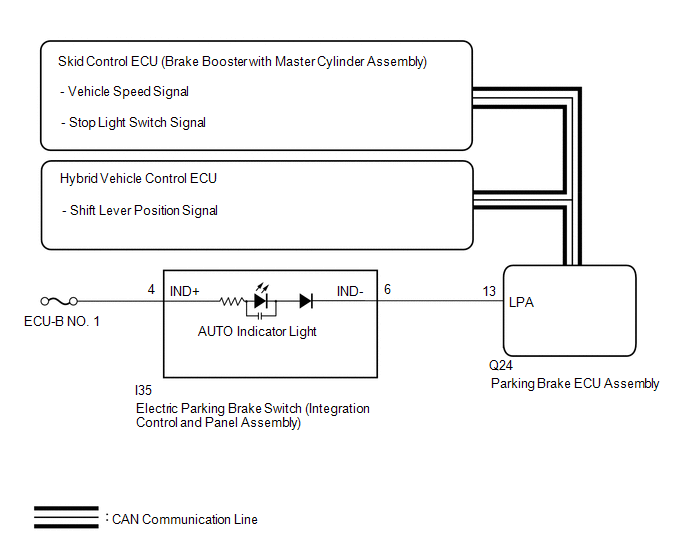
The parking brake ECU assembly receives shift position information from the hybrid vehicle control ECU via CAN communication. Also, the parking brake ECU assembly receives wheel speed information and stop light switch information from the skid control ECU (brake booster with master cylinder assembly).
The electric parking brake system AUTO control (shift-linked) function automatically releases the parking brake when the following conditions are met: 1) Power switch on (IG), 2) brake pedal depressed, and 3) shift lever moved out of P. Also, when the shift lever is moved to P with the vehicle in this condition, the function automatically locks the parking brake.
WIRING DIAGRAM
CAUTION / NOTICE / HINT
NOTICE:
- Before disconnecting connectors or fuses, turn the power switch off and wait 20 seconds or more.
- When replacing the parking brake ECU assembly, operate the electric parking brake switch (integration control and panel assembly), as the parking brake indicator light (red) blinks when the power switch is first turned on (IG).
PROCEDURE
| 1. | CHECK DTC (CAN COMMUNICATION SYSTEM) |
(a) Check for DTCs.
Click here .gif)
| DTC is output | .gif) | GO TO CAN COMMUNICATION SYSTEM |
|
.gif)
| 2. | READ VALUE USING TECHSTREAM (AUTO MODE) |
(a) Turn the power switch off.
(b) Connect the Techstream to the DLC3.
(c) Turn the power switch on (IG) and the Techstream on.
(d) Enter the following menus: Chassis / Electric Parking Brake / Data List.
(e) Check the values by referring to the table below.
Chassis > Electric Parking Brake > Data List| Tester Display | Measurement Item | Range | Normal Condition |
|---|---|---|---|
| Auto Mode | AUTO (shift-linked) mode permission display | ON or OFF | ON: AUTO (shift-linked) mode OFF: Manual mode |
| Tester Display |
|---|
| Auto Mode |
(f) When switching the mode, check that the Data List display turns on and off.
HINT:
For details regarding mode switching: Click here
| Result | Proceed to |
|---|---|
| The Data List display does not turn on and off according to mode switching | A |
| The Data List display turns on and off according to mode switching | B |
| B | | GO TO STEP 5 |
|
| 3. | INSPECT ELECTRIC PARKING BRAKE SWITCH (INTEGRATION CONTROL AND PANEL ASSEMBLY) |
(a) Remove the electric parking brake switch (integration control and panel assembly).
Click here
(b) Inspect the electric parking brake switch (integration control and panel assembly).
Click here
| NG | | REPLACE INTEGRATION CONTROL AND PANEL ASSEMBLY |
|
| 4. | CHECK HARNESS AND CONNECTOR (PARKING BRAKE ECU ASSEMBLY - ELECTRIC PARKING BRAKE SWITCH (INTEGRATION CONTROL AND PANEL ASSEMBLY)) |
(a) Disconnect the I35 electric parking brake switch (integration control and panel assembly) connector.
(b) Disconnect the Q24 parking brake ECU assembly connector.
(c) Measure the resistance according to the value(s) in the table below.
Standard Resistance:
| Tester Connection | Condition | Specified Condition |
|---|---|---|
| Q24-20 (LCK1) - I35-9 (LOK1) | Always | Below 5 Ω |
| Q24-15 (LCK2) - I35-10 (LOK2) | Always | Below 5 Ω |
| Q24-20 (LCK1) or I35-9 (LOK1) - Body ground | Always | 10 kΩ or higher |
| Q24-15 (LCK2) or I35-10 (LOK2) - Body ground | Always | 10 kΩ or higher |
| Q24-19 (REL1) - I35-1 (RLS1) | Always | Below 5 Ω |
| Q24-16 (REL2) - I35-2 (RLS2) | Always | Below 5 Ω |
| Q24-19 (REL1) or I35-1 (RLS1) - Body ground | Always | 10 kΩ or higher |
| Q24-16 (REL2) or I35-2 (RLS2) - Body ground | Always | 10 kΩ or higher |
| I35-16 (GND1) - Body ground | Always | Below 5 Ω |
| NG | | REPAIR OR REPLACE HARNESS OR CONNECTOR |
|
| 5. | READ VALUE USING TECHSTREAM (P / N / R / D POSITION) |
(a) Turn the power switch off.
(b) Connect the Techstream to the DLC3.
(c) Turn the power switch on (IG) and the Techstream on.
(d) Enter the following menus: Chassis / Electric Parking Brake / Data List.
(e) Check the values by referring to the table below.
Chassis > Electric Parking Brake > Data List| Tester Display | Measurement Item | Range | Normal Condition |
|---|---|---|---|
| P Position | Shift lever position input information display | ON or OFF | ON: Shift lever is in P OFF: Shift lever is not in P |
| N Position | Shift lever position input information display | ON or OFF | ON: Shift lever is in N OFF: Shift lever is not in N |
| R Position | Shift lever position input information display | ON or OFF | ON: Shift lever is in R OFF: Shift lever is not in R |
| D Position | Shift lever position input information display | ON or OFF | ON: Shift lever is in D or S OFF: Shift lever is not in D or S |
| Tester Display |
|---|
| P Position |
| N Position |
| R Position |
| D Position |
(f) Check that the Data List display turns on and off according to the shift lever operation.
OK:
Data List display turns on and off according to shift lever operation.
| NG | | GO TO HYBRID CONTROL SYSTEM |
|
| 6. | READ VALUE USING TECHSTREAM (STOP LIGHT SWITCH) |
(a) Turn the power switch off.
(b) Connect the Techstream to the DLC3.
(c) Turn the power switch on (IG) and the Techstream on.
(d) Enter the following menus: Chassis / Electric Parking Brake / Data List.
(e) Check the values by referring to the table below.
Chassis > Electric Parking Brake > Data List| Tester Display | Measurement Item | Range | Normal Condition |
|---|---|---|---|
| Stop Light Switch | Stop light switch assembly input information display | ON or OFF | ON: Brake pedal depressed OFF: Brake pedal released |
| Tester Display |
|---|
| Stop Light Switch |
(f) Check that the Data List display turns on and off according to the brake pedal operation (depressed and released).
OK:
On the Techstream screen, item changes between ON and OFF according to switch operation.
| OK | | REPLACE PARKING BRAKE ECU ASSEMBLY |
| NG | | GO TO ELECTRONICALLY CONTROLLED BRAKE SYSTEM |
READ NEXT:
 Electric Parking Brake AUTO Indicator Light Circuit
WIRING DIAGRAM CAUTION / NOTICE / HINT NOTICE:
Inspect the fuses for circuits related to this system before performing the following inspection procedure.
Before disconnecting connectors or fuse
Forced Release
Operation MethodOPERATION METHOD PROCEDURE 1. PARKING BRAKE FORCED RELEASE NOTICE: Follow the procedures when using SST to release the parking brake. If the parking brake cannot be released, follow t
Parking Brake System
PrecautionPRECAUTION CAUTION: Perform each part replacement carefully, as mistakes could affect the brake system performance and lead to driving problems. When replacing a part, replace with the same
SEE MORE:
IG Power Supply Voltage (C1551)
DESCRIPTION The power steering ECU assembly distinguishes the power switch status as on (IG) or off through the IG power source circuit. DTC No. Detection Item DTC Detection Condition Trouble Area Warning Indicate Return-to-normal Condition Note C1551 IG Power Supply Voltage I
Battery Control System (P3000-388)
DESCRIPTION The hybrid vehicle control ECU alerts the driver and performs fail-safe control based on error signals received from the battery voltage sensor. This DTC is stored when the SOC (state of charge) of the HV battery starts to drop as a result of leaving the shift lever in N, running out of
