Lexus NX: IG Power Supply Voltage (C1551)
DESCRIPTION
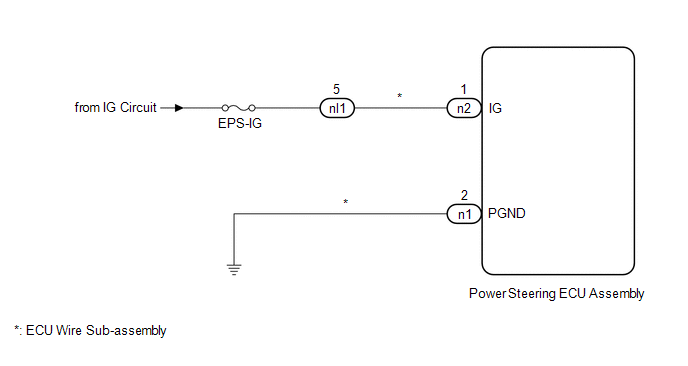
The power steering ECU assembly distinguishes the power switch status as on (IG) or off through the IG power source circuit.
| DTC No. | Detection Item | DTC Detection Condition | Trouble Area | Warning Indicate | Return-to-normal Condition | Note |
|---|---|---|---|---|---|---|
| C1551 | IG Power Supply Voltage | IG power source circuit malfunction inside ECU |
| On | After normal confirmation | - |
WIRING DIAGRAM
CAUTION / NOTICE / HINT
NOTICE:
If the power steering ECU assembly has been replaced, perform assist map writing and torque sensor zero point calibration.
Click here .gif)
HINT:
Inspect the fuses for circuits related to this system before performing the following procedure.
PROCEDURE
| 1. | CHECK CONNECTOR CONNECTION CONDITION AND GROUND WIRE |
(a) Check the connection condition of the ECU wire sub-assembly and power steering ECU assembly connectors.
OK:
The ECU wire sub-assembly and power steering ECU assembly connectors are securely connected.
(b) Check that the ground wire is securely installed with the bolt.
Click here
OK:
The ground wire is securely installed with the bolt.
| NG | .gif) | CONNECT CONNECTOR OR INSTALL GROUND WIRE |
|
.gif)
| 2. | READ VALUE USING TECHSTREAM (IG POWER SUPPLY) |
(a) Turn the power switch off.
(b) Connect the Techstream to the DLC3.
(c) Turn the power switch on (IG).
(d) Turn the Techstream on.
(e) Enter the following menus: Chassis / EMPS / Data List.
(f) Select the item "IG power supply" in the Data List and read the value displayed on the Techstream.
Chassis > EMPS > Data List| Tester Display | Measurement Item | Range | Normal Condition | Diagnostic Note |
|---|---|---|---|---|
| IG Power Supply | ECU power source voltage | Min.: 0.0000 V Max.: 20.1531 V | Power switch on (IG): 8 to 16 V | - |
| Tester Display |
|---|
| IG Power Supply |
OK:
The normal condition value is displayed on the Techstream.
| OK | | CHECK INTERMITTENT PROBLEMS |
|
| 3. | CHECK HARNESS AND CONNECTOR (IG POWER SUPPLY) |
| (a) Disconnect the nl1 ECU wire sub-assembly connector. |
|
.png)
(b) Turn the power switch on (IG).
(c) Measure the voltage according to the value(s) in the table below.
Standard Voltage:
| Tester Connection | Switch Condition | Specified Condition |
|---|---|---|
| nl1-5 (IG) - Body ground | Power switch on (IG) | 8 to 16 V |
| NG | | REPAIR OR REPLACE HARNESS OR CONNECTOR |
|
| 4. | CHECK ECU WIRE SUB-ASSEMBLY |
| (a) Connect the nl1 connector to the ECU wire sub-assembly. |
|
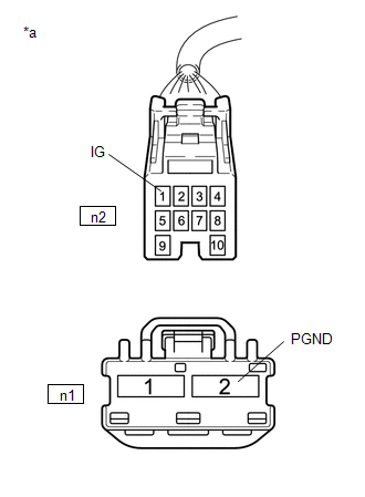
(b) Disconnect the n2 and n1 power steering ECU assembly connectors.
(c) Turn the power switch on (IG).
(d) Measure the voltage according to the value(s) in the table below.
Standard Voltage:
| Tester Connection | Switch Condition | Specified Condition |
|---|---|---|
| n2-1 (IG) - Body ground | Power switch on (IG) | 8 to 16 V |
(e) Turn the power switch off.
(f) Measure the resistance according to the value(s) in the table below.
Standard Resistance:
| Tester Connection | Condition | Specified Condition |
|---|---|---|
| n1-2 (PGND) - Body ground | Always | Below 1 Ω |
| OK | | REPLACE POWER STEERING ECU ASSEMBLY |
| NG | | REPAIR OR REPLACE ECU WIRE SUB-ASSEMBLY |
READ NEXT:
 PIG Power Supply Voltage (C1552,C1554)
DESCRIPTION When a problem occurs in the power steering system, the power source relay circuit is shut off to stop the power assist. DTC No. Detection Item DTC Detection Condition Trouble Are
Error in Matching of ECUs (C1567)
DESCRIPTION Based on the ECM signal, the power steering ECU assembly determines if the correct type of ECM is installed. DTC No. Detection Item DTC Detection Condition Trouble Area Warning
Assist Map Number Un-Writing (C1581)
DESCRIPTION This DTC will be stored if the power steering ECU assembly determines that the assist map is not written in the ECU. DTC No. Detection Item DTC Detection Condition Trouble Area
SEE MORE:
Inspection
INSPECTION PROCEDURE 1. INSPECT FRONT LOWER BALL JOINT ASSEMBLY LH (a) Inspect the turning torque of the ball joint. (1) Secure the front lower ball joint in a vise using aluminum plates. (2) Install the nut to the front lower ball joint stud. (3) Move the stud back and forth several times. Using
Power Outlet Socket
ComponentsCOMPONENTS ILLUSTRATION *A w/ Rear Seat Heater - - *1 CIGARETTE LIGHTER COVER *2 NO. 2 POWER OUTLET SOCKET ASSEMBLY *3 REAR CONSOLE END PANEL SUB-ASSEMBLY - - RemovalREMOVAL PROCEDURE 1. REMOVE REAR CONSOLE END PANEL SUB-ASSEMBLY Click here 2. REMOVE C
