- DTC judgment completed
- System normal
Lexus NX: Engine Coolant Temperature Circuit (P0115,P0117,P0118)
Lexus NX Service Manual / Engine & Hybrid System / 2ar-fxe (engine Control) / Sfi System / Engine Coolant Temperature Circuit (P0115,P0117,P0118)
DESCRIPTION
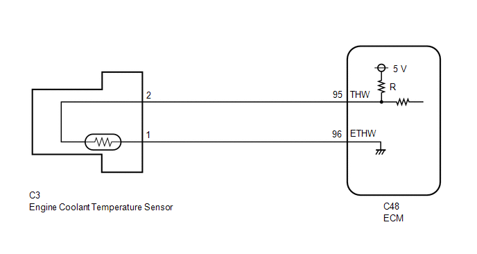
A thermistor, whose resistance value varies according to the engine coolant temperature, is built into the engine coolant temperature sensor. The structure of the sensor and its connection to the ECM are the same as those of the intake air temperature sensor.
HINT:
When DTC P0115, P0117 or P0118 is stored, the ECM enters fail-safe mode. During fail-safe mode, the engine coolant temperature is estimated to be 80°C (176°F) by the ECM. Fail-safe mode continues until a pass condition is detected.
| DTC No. | Detection Item | DTC Detection Condition | Trouble Area | MIL | Memory |
|---|---|---|---|---|---|
| P0115 | Engine Coolant Temperature Circuit | An open or short in the engine coolant temperature sensor circuit for 0.5 seconds (1 trip detection logic). |
| Comes on | DTC stored |
| P0117 | Engine Coolant Temperature Circuit Low Input | A short in the engine coolant temperature sensor circuit for 0.5 seconds (1 trip detection logic). |
| Comes on | DTC stored |
| P0118 | Engine Coolant Temperature Circuit High Input | An open in the engine coolant temperature sensor circuit for 0.5 seconds (1 trip detection logic). |
| Comes on | DTC stored |
HINT:
When any of these DTCs are output, check the engine coolant temperature using the Techstream. Enter the following menus: Powertrain / Engine and ECT / Data List / Primary / Coolant Temp.
| Temperature Displayed | Malfunction |
|---|---|
| -40°C (-40°F) | Open circuit |
| Higher than 135°C (275°F) | Short circuit |
MONITOR DESCRIPTION
The engine coolant temperature sensor is used to monitor the engine coolant temperature. The engine coolant temperature sensor has a thermistor with a resistance that varies according to the temperature of the engine coolant. When the coolant temperature is low, the resistance in the thermistor increases. When the temperature is high, the resistance drops. These variations in resistance are reflected in the output voltage from the sensor. The ECM monitors the sensor voltage and uses this value to calculate the engine coolant temperature. If the sensor output voltage deviates from the normal operating range, the ECM interprets this as a fault in the engine coolant temperature sensor circuit and stores a DTC.
Example:
If the sensor output voltage is higher than 4.91 V for 0.5 seconds or more, the ECM determines that there is an open in the engine coolant temperature sensor circuit, and stores DTC P0118. Conversely, if the voltage output is less than 0.14 V for 0.5 seconds or more, the ECM determines that there is a short in the sensor circuit, and stores DTC P0117.
MONITOR STRATEGY
| Related DTCs | P0115: Engine coolant temperature sensor range check (chattering) P0117: Engine coolant temperature sensor range check (low voltage) P0118: Engine coolant temperature sensor range check (high voltage) |
| Required Sensors/Components (Main) | Engine coolant temperature sensor |
| Required Sensors/Components (Related) | - |
| Frequency of Operation | Continuous |
| Duration | 0.5 seconds |
| MIL Operation | Immediate |
| Sequence of Operation | None |
TYPICAL ENABLING CONDITIONS
| Monitor runs whenever the following DTCs are not stored | None |
TYPICAL MALFUNCTION THRESHOLDS
P0115| Engine coolant temperature sensor voltage [Engine coolant temperature] | Less than 0.14 V, or higher than 4.91 V [Higher than 135°C (275°F), or less than -60°C (-76°F)] |
| Engine coolant temperature sensor voltage [Engine coolant temperature] | Less than 0.14 V [Higher than 135°C (275°F)] |
| Engine coolant temperature sensor voltage [Engine coolant temperature] | Higher than 4.91 V [Less than -60°C (-76°F)] |
COMPONENT OPERATING RANGE
| Engine coolant temperature sensor voltage [Engine coolant temperature] | 0.14 to 4.91 V [-60 to 135°C (-76 to 275°F)] |
CONFIRMATION DRIVING PATTERN
- Connect the Techstream to the DLC3.
- Turn the power switch on (IG) and turn the Techstream on.
- Clear the DTCs (even if no DTCs are stored, perform the clear DTC procedure).
- Turn the power switch off and wait for at least 30 seconds.
- Turn the power switch on (IG) and turn the Techstream on.
- Wait 0.5 seconds or more.
- Enter the following menus: Powertrain / Engine and ECT / Trouble Codes.
-
Read the pending DTCs.
HINT:
- If a pending DTC is output, the system is malfunctioning.
- If a pending DTC is not output, perform the following procedure.
- Enter the following menus: Powertrain / Engine and ECT / Utility / All Readiness.
- Input the DTC: P0115, P0117 or P0118.
-
Check the DTC judgment result.
Techstream Display
Description
NORMAL
ABNORMAL
- DTC judgment completed
- System abnormal
INCOMPLETE
- DTC judgment not completed
- Perform driving pattern after confirming DTC enabling conditions
N/A
- Unable to perform DTC judgment
- Number of DTCs which do not fulfill DTC preconditions has reached ECU memory limit
HINT:
- If the judgment result shows NORMAL, the system is normal.
- If the judgment result shows ABNORMAL, the system has a malfunction.
-
If the judgment result is INCOMPLETE or N/A and no pending DTC is output, perform a universal trip and check for permanent DTCs.
Click here
.gif)
HINT:
- If a permanent DTC is output, the system is malfunctioning.
- If no permanent DTC is output, the system is normal.
WIRING DIAGRAM
CAUTION / NOTICE / HINT
HINT:
- If DTC P0117 is stored, check that the engine does not overheat (the DTC P0117 may be stored due to engine overheating).
- Read freeze frame data using the Techstream. The ECM records vehicle and driving condition information as freeze frame data the moment a DTC is stored. When troubleshooting, freeze frame data can help determine if the vehicle was moving or stationary, if the engine was warmed up or not, if the air fuel ratio was lean or rich, and other data from the time the malfunction occurred.
PROCEDURE
| 1. | READ VALUE USING TECHSTREAM (COOLANT TEMP) |
(a) Connect the Techstream to the DLC3.
(b) Turn the power switch on (IG).
(c) Turn the Techstream on.
(d) Enter the following menus: Powertrain / Engine and ECT / Data List / Primary / Coolant Temp.
Powertrain > Engine and ECT > Data List| Tester Display |
|---|
| Coolant Temp |
(e) Read the value displayed on the Techstream.
Standard value:
Between 75 and 100°C (167 and 212°F) with warm engine.
| Result | Proceed to |
|---|---|
| -40°C (-40°F) | A |
| Higher than 135°C (275°F) | B |
| Between 75 and 100°C (167 and 212°F) | C |
HINT:
- If there is an open circuit, the Techstream indicates -40°C (-40°F).
- If there is a short circuit, the Techstream indicates higher than 135°C (275°F).
| B | .gif) | GO TO STEP 4 |
| C | | CHECK FOR INTERMITTENT PROBLEMS |
|
.gif)
| 2. | READ VALUE USING TECHSTREAM (CHECK FOR OPEN IN WIRE HARNESS) |
(a) Disconnect the engine coolant temperature sensor connector.
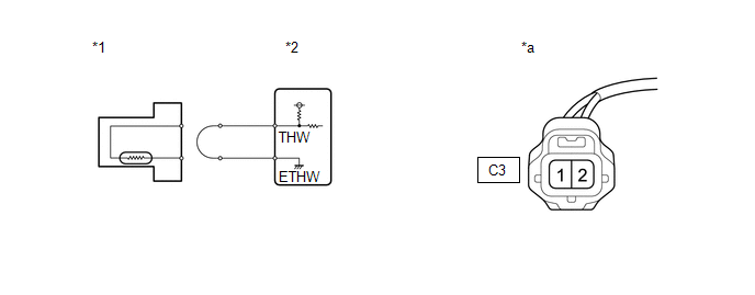
| *1 | Engine Coolant Temperature Sensor | *2 | ECM |
| *a | Front view of wire harness connector (to Engine Coolant Temperature Sensor) | - | - |
(b) Connect terminals C3-1 and C3-2 of the engine coolant temperature sensor connector on the wire harness side.
(c) Connect the Techstream to the DLC3.
(d) Turn the power switch on (IG).
(e) Turn the Techstream on.
(f) Enter the following menus: Powertrain / Engine and ECT / Data List / Primary / Coolant Temp.
Powertrain > Engine and ECT > Data List| Tester Display |
|---|
| Coolant Temp |
(g) Read the value displayed on the Techstream.
Standard value:
Higher than 135°C (275°F)
HINT:
Perform "Inspection After Repair" after replacing the engine coolant temperature sensor.
Click here
| OK | | REPLACE ENGINE COOLANT TEMPERATURE SENSOR |
|
| 3. | CHECK HARNESS AND CONNECTOR (ENGINE COOLANT TEMPERATURE SENSOR - ECM) |
(a) Disconnect the engine coolant temperature sensor connector.
(b) Disconnect the ECM connector.
(c) Measure the resistance according to the value(s) in the table below.
Standard Resistance:
| Tester Connection | Condition | Specified Condition |
|---|---|---|
| C3-2 - C48-95 (THW) | Always | Below 1 Ω |
| C3-1 - C48-96 (ETHW) | Always | Below 1 Ω |
| OK | | REPLACE ECM |
| NG | | REPAIR OR REPLACE HARNESS OR CONNECTOR |
| 4. | READ VALUE USING TECHSTREAM (CHECK FOR SHORT IN WIRE HARNESS) |
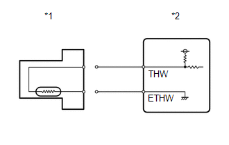
| *1 | Engine Coolant Temperature Sensor |
| *2 | ECM |
(a) Disconnect the engine coolant temperature sensor connector.
(b) Connect the Techstream to the DLC3.
(c) Turn the power switch on (IG).
(d) Turn the Techstream on.
(e) Enter the following menus: Powertrain / Engine and ECT / Data List / Primary / Coolant Temp.
Powertrain > Engine and ECT > Data List| Tester Display |
|---|
| Coolant Temp |
(f) Read the value displayed on the Techstream.
Standard value:
-40°C (-40°F)
HINT:
Perform "Inspection After Repair" after replacing the engine coolant temperature sensor.
Click here
| OK | | REPLACE ENGINE COOLANT TEMPERATURE SENSOR |
|
| 5. | CHECK HARNESS AND CONNECTOR (ENGINE COOLANT TEMPERATURE SENSOR - ECM) |
(a) Disconnect the engine coolant temperature sensor connector.
(b) Disconnect the ECM connector.
(c) Measure the resistance according to the value(s) in the table below.
Standard Resistance:
| Tester Connection | Condition | Specified Condition |
|---|---|---|
| C3-2 or C48-95 (THW) - Body ground | Always | 10 kΩ or higher |
| OK | | REPLACE ECM |
| NG | | REPAIR OR REPLACE HARNESS OR CONNECTOR |
READ NEXT:
 Engine Coolant Temperature Circuit Range / Performance (P0116)
DESCRIPTION Refer to DTC P0115. Click here DTC No. Detection Item DTC Detection Condition Trouble Area MIL Memory P0116 Engine Coolant Temperature Circuit Range / Performance Ei
Engine Coolant Temperature / Intake Air Temperature Correlation (P011B)
DESCRIPTION The engine has two temperature sensors, an engine coolant temperature sensor and an intake air temperature sensor, to detect temperature while the engine is operating. A thermistor, whose
Throttle Pedal Position Sensor / Switch "A" Circuit (P0120-P0123,P0220,P0222,P0223,P2135)
DESCRIPTION HINT: These DTCs relate to the throttle position sensor. The throttle position sensor is mounted on the throttle body with motor assembly and detects the opening angle of the throttle valv
SEE MORE:
Utility
UTILITY FREEZE FRAME DATA NOTICE:
Freeze frame data is stored and updated each time the brakes are operated. Only the latest 30 sets of data are stored.
Using the Techstream, make sure to save the data before performing a reproduction test as the data will be updated. HINT: The freeze frame dat
Portable Player cannot be Operated Using In-vehicle Device or Track Information is not Displayed on In-vehicle Device
PROCEDURE 1. CHECK USING ANOTHER "Bluetooth" AUDIO COMPATIBLE VEHICLE OF SAME MODEL (a) Check if track information is displayed normally on another "Bluetooth" audio compatible vehicle of the same model. OK: Track information is displayed normally. OK PROCEED TO NEXT SUSPECTED AREA
© 2016-2026 Copyright www.lexunx.com
