- DTC judgment completed
- System normal
Lexus NX: Throttle Pedal Position Sensor / Switch "A" Circuit (P0120-P0123,P0220,P0222,P0223,P2135)
Lexus NX Service Manual / Engine & Hybrid System / 2ar-fxe (engine Control) / Sfi System / Throttle Pedal Position Sensor / Switch "A" Circuit (P0120-P0123,P0220,P0222,P0223,P2135)
DESCRIPTION
HINT:
These DTCs relate to the throttle position sensor.
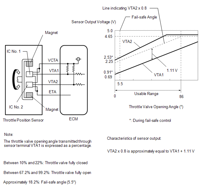
The throttle position sensor is mounted on the throttle body with motor assembly and detects the opening angle of the throttle valve. This sensor is a non-contact type sensor. It uses Hall-effect elements in order to yield accurate signals even in extreme driving conditions, such as at high speeds as well as very low speeds.
The throttle position sensor has 2 sensor circuits, VTA1 and VTA2 each of which transmits a signal. VTA1 is used to detect the throttle valve angle and VTA2 is used to detect malfunctions in VTA1. The sensor signal voltages vary between 0 V and 5 V in proportion to the throttle valve opening angle, and are transmitted to the VTA1 and VTA2 terminals of the ECM.
As the valve closes, the sensor output voltage decreases and as the valve opens, the sensor output voltage increases. The ECM calculates the throttle valve opening angle according to these signals and controls the throttle actuator in response to a request from the hybrid system. These signals are also used in calculations such as air fuel ratio correction, power increase correction and fuel-cut control.
| DTC No. | Detection Item | DTC Detection Condition | Trouble Area | MIL | Memory |
|---|---|---|---|---|---|
| P0120 | Throttle Pedal Position Sensor / Switch "A" Circuit | The output voltage of VTA1 quickly fluctuates beyond the lower and upper malfunction thresholds for 2 seconds or more (1 trip detection logic). |
| Comes on | DTC stored |
| P0121 | Throttle Pedal Position Sensor / Switch "A" Circuit Range / Performance | The difference between the output voltages of VTA1 and VTA2 is less than 0.8 V, or higher than 1.6 V for 2 seconds (1 trip detection logic). |
| Comes on | DTC stored |
| P0122 | Throttle / Pedal Position Sensor / Switch "A" Circuit Low Input | The output voltage of VTA1 is 0.2 V or less for 2 seconds or more (1 trip detection logic). |
| Comes on | DTC stored |
| P0123 | Throttle / Pedal Position Sensor / Switch "A" Circuit High Input | The output voltage of VTA1 is 4.535 V or higher for 2 seconds or more (1 trip detection logic). |
| Comes on | DTC stored |
| P0220 | Throttle / Pedal Position Sensor / Switch "B" Circuit | The output voltage of VTA2 quickly fluctuates beyond the lower and upper malfunction thresholds for 2 seconds or more (1 trip detection logic). |
| Comes on | DTC stored |
| P0222 | Throttle / Pedal Position Sensor / Switch "B" Circuit Low Input | The output voltage of VTA2 is 1.75 V or less for 2 seconds or more (1 trip detection logic). |
| Comes on | DTC stored |
| P0223 | Throttle / Pedal Position Sensor / Switch "B" Circuit High Input | The output voltage of VTA2 is 4.8 V or higher, and VTA1 is between 0.2 V and 2.02 V for 2 seconds or more (1 trip detection logic). |
| Comes on | DTC stored |
| P2135 | Throttle / Pedal Position Sensor / Switch "A" / "B" Voltage Correlation | Either of the following conditions is met (1 trip detection logic): (a) The difference between the output voltages of VTA1 and VTA2 is 0.02 V or less for 0.5 seconds or more. (b) The output voltage of VTA1 is 0.2 V or less, and VTA2 is 1.75 V or less for 0.4 seconds or more. |
| Comes on | DTC stored |
HINT:
- When any of these DTCs are output, check the throttle valve opening angle using the Techstream. Enter the following menus: Powertrain / Engine and ECT / Data List / Gas Throttle / Throttle Position No.1 and Throttle Position No.2.
-
Throttle Position No.1 is the VTA1 signal, and Throttle Position No.2 is the VTA2 signal.
Reference (Normal Condition):
Techstream Display
Accelerator Pedal Fully Released
Accelerator Pedal Fully Depressed
Throttle Position No.1
0.5 to 1.1 V
3.2 to 4.8 V
Throttle Position No.2
2.1 to 3.1 V
4.6 to 4.98 V
MONITOR DESCRIPTION
The ECM uses the throttle position sensor to monitor the throttle valve opening angle. There are several checks that the ECM performs to confirm the proper operation of the throttle position sensor.
P0120, P0122, P0123, P0220, P0222, P0223 and P2135:
- A specific voltage difference is expected between the sensor terminals, VTA1 and VTA2, for each throttle valve opening angle. If the difference between VTA1 and VTA2 is incorrect, the ECM interprets this as a malfunction in the sensor circuit, and stores a DTC.
- VTA1 and VTA2 each have a specific voltage range. If VTA1 or VTA2 is outside the normal operating range, the ECM interprets this as a malfunction in the sensor circuit, and stores a DTC.
- VTA1 and VTA2 should never be close to the same voltage level. If VTA1 is within 0.02 V of VTA2, the ECM determines that there is a short in the sensor circuit, and stores a DTC.
P0121:
-
This sensor transmits two signals: VTA1 and VTA2. VTA1 is used to detect the throttle opening angle and VTA2 is used to detect malfunctions in VTA1. The ECM performs several checks to confirm the proper operation of the throttle position sensor and VTA1.
For each throttle opening angle, a specific voltage difference is expected between the outputs of VTA1 and VTA2. If the output voltage difference between the two signals deviates from the normal operating range, the ECM interprets this as a malfunction in the throttle position sensor. In this case the ECM will illuminate the MIL and store this DTC.
MONITOR STRATEGY
| Related DTCs | P0120: Throttle position sensor 1 range check (chattering) P0121: Throttle position sensor rationality P0122: Throttle position sensor 1 range check (low voltage) P0123: Throttle position sensor 1 range check (high voltage) P0220: Throttle position sensor 2 range check (chattering) P0222: Throttle position sensor 2 range check (low voltage) P0223: Throttle position sensor 2 range check (high voltage) P2135: Throttle position sensor range check (correlation) |
| Required Sensors/Components (Main) | Throttle position sensor |
| Required Sensors/Components (Related) | - |
| Frequency of Operation | Continuous |
| Duration | 2 seconds: P0120, P0122, P0123, P0220, P0222 and P0223 Within 2 seconds: P0121 0.5 seconds: P2135 (Case 1) 0.4 seconds: P2135 (Case 2) |
| MIL Operation | Immediate |
| Sequence of Operation | None |
TYPICAL ENABLING CONDITIONS
All| Monitor runs whenever the following DTCs are not stored | None |
| Either of the following conditions is met | A or B |
| A. Power switch off to on (IG) | 0.012 seconds or more |
| B. Throttle actuator power | On |
| Either of the following conditions is met | A or B |
| A. Power switch | On (IG) |
| B. Throttle actuator power | On |
| Throttle position sensor circuit fail (P0120, P0122, P0123, P0220, P0222, P0223, P2135) | Not detected |
TYPICAL MALFUNCTION THRESHOLDS
P0120| VTA1 voltage | 0.2 V or less, or 4.535 V or higher |
| Either of the following conditions is met | A or B |
| A. Difference of learned throttle position sensor opener position voltage between VTA2 and VTA1 | Higher than 1.6 V |
| B. Difference of learned throttle position sensor opener position voltage between VTA2 and VTA1 | Lower than 0.8 V |
| VTA1 voltage | 0.2 V or less |
| VTA1 voltage | 4.535 V or higher |
| Either of the following conditions is met | A or B |
| A. VTA2 voltage | 1.75 V or less |
| B. VTA2 voltage when VTA1 0.2 V to 2.02 V | 4.8 V or higher |
| VTA2 voltage | 1.75 V or less |
| VTA2 voltage when VTA1 0.2 V to 2.02 V | 4.8 V or higher |
| Difference between VTA1 and VTA2 voltages | 0.02 V or less |
| Both of the following conditions are met | - |
| VTA1 voltage | 0.2 V or less |
| VTA2 voltage | 1.75 V or less |
COMPONENT OPERATING RANGE
| All of the following conditions are met | - |
| VTA1 voltage | Higher than 0.2 V, and less than 4.535 V |
| VTA2 voltage | Higher than 1.75 V, and less than 4.8 V |
| Difference between VTA1 and VTA2 voltages | Higher than 0.02 V |
CONFIRMATION DRIVING PATTERN
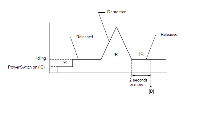
- Connect the Techstream to the DLC3.
- Turn the power switch on (IG) and turn the Techstream on.
- Clear the DTCs (even if no DTCs are stored, perform the clear DTC procedure).
- Turn the power switch off and wait for at least 30 seconds.
- Turn the power switch on (IG) and turn the Techstream on [A].
-
Put the engine in inspection mode (maintenance mode).
Click here
.gif)
- Start the engine.
- With the vehicle stationary, fully depress and release the accelerator pedal [B].
- Idle the engine for 2 seconds or more [C].
- Enter the following menus: Powertrain / Engine and ECT / Trouble Codes [D].
-
Read the pending DTCs.
HINT:
- If a pending DTC is output, the system is malfunctioning.
- If a pending DTC is not output, perform the following procedure.
- Enter the following menus: Powertrain / Engine and ECT / Utility / All Readiness.
- Input the DTC: P0120, P0121, P0122, P0123, P0220, P0222, P0223 or P2135.
-
Check the DTC judgment result.
Techstream Display
Description
NORMAL
ABNORMAL
- DTC judgment completed
- System abnormal
INCOMPLETE
- DTC judgment not completed
- Perform driving pattern after confirming DTC enabling conditions
N/A
- Unable to perform DTC judgment
- Number of DTCs which do not fulfill DTC preconditions has reached ECU memory limit
HINT:
- If the judgment result shows NORMAL, the system is normal.
- If the judgment result shows ABNORMAL, the system has a malfunction.
- If the judgment result shows INCOMPLETE or N/A, perform steps [B] through [D] again.
-
If no pending DTC is output, perform a universal trip and check for permanent DTCs.
Click here
HINT:
- If a permanent DTC is output, the system is malfunctioning.
- If no permanent DTC is output, the system is normal.
FAIL-SAFE
When any of these DTCs or other DTCs relating to Electronic Throttle Control System (ETCS) malfunctions are stored, the ECM enters fail-safe mode. During fail-safe mode, the ECM cuts the current to the throttle actuator, and the throttle valve is returned to a 5.5° throttle valve opening angle by the return spring. The ECM stops the engine and the vehicle can be driven using solely the hybrid system. If the accelerator pedal is depressed firmly and gently, the vehicle can be driven slowly.
Fail-safe mode continues until a pass condition is detected, and the power switch is turned off.
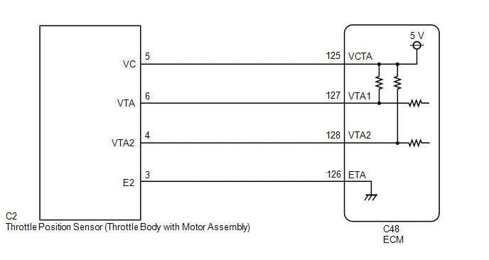
WIRING DIAGRAM
CAUTION / NOTICE / HINT
HINT:
-
DTC P0121 is stored when the VTA and VTA2 output voltages are not consistent with the sensor characteristics. Therefore, check the freeze frame data when this DTC is stored. Use the following formula to confirm the relative differences in voltage.
Calculate the voltage of VTA and VTA2 according to Throttle Sensor Volt % and Throttle Sensor #2 Volt % respectively and confirm their consistency.
Example:
Throttle Sensor Volt % / 100 (%) x 5 (V) = Throttle Position No.1
Characteristic Sensor Output:
VTA2 x 0.8 is approximately equal to VTA1 + 1.11 V
VTA1: Throttle Position No.1
VTA2: Throttle Position No.2
- Read freeze frame data using the Techstream. The ECM records vehicle and driving condition information as freeze frame data the moment a DTC is stored. When troubleshooting, freeze frame data can help determine if the vehicle was moving or stationary, if the engine was warmed up or not, if the air fuel ratio was lean or rich, and other data from the time the malfunction occurred.
PROCEDURE
| 1. | CHECK HARNESS AND CONNECTOR (THROTTLE POSITION SENSOR - ECM) |
(a) Disconnect the throttle body with motor assembly connector.
(b) Disconnect the ECM connector.
(c) Measure the resistance according to the value(s) in the table below.
Standard Resistance:
| Tester Connection | Condition | Specified Condition |
|---|---|---|
| C2-5 (VC) - C48-125 (VCTA) | Always | Below 1 Ω |
| C2-6 (VTA) - C48-127 (VTA1) | Always | Below 1 Ω |
| C2-4 (VTA2) - C48-128 (VTA2) | Always | Below 1 Ω |
| C2-3 (E2) - C48-126 (ETA) | Always | Below 1 Ω |
| C2-5 (VC) or C48-125 (VCTA) - Body ground | Always | 10 kΩ or higher |
| C2-6 (VTA) or C48-127 (VTA1) - Body ground | Always | 10 kΩ or higher |
| C2-4 (VTA2) or C48-128 (VTA2) - Body ground | Always | 10 kΩ or higher |
| NG | .gif) | REPAIR OR REPLACE HARNESS OR CONNECTOR |
|
.gif)
| 2. | INSPECT ECM (VC VOLTAGE) |
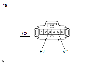
| *a | Front view of wire harness connector (to Throttle Body with Motor Assembly) |
(a) Disconnect the throttle body with motor assembly connector.
(b) Turn the power switch on (IG).
(c) Measure the voltage according to the value(s) in the table below.
Standard Voltage:
| Tester Connection | Condition | Specified Condition |
|---|---|---|
| C2-5 (VC) - C2-3 (E2) | Power switch on (IG) | 4.5 to 5.5 V |
| NG | | REPLACE ECM |
|
| 3. | REPLACE THROTTLE BODY WITH MOTOR ASSEMBLY |
(a) Replace the throttle body with motor assembly.
Click here
HINT:
Perform "Inspection After Repair" after replacing the throttle body with motor assembly.
Click here
|
| 4. | CHECK WHETHER DTC OUTPUT RECURS (THROTTLE POSITION SENSOR DTCS) |
(a) Connect the Techstream to the DLC3.
(b) Turn the power switch on (IG).
(c) Turn the Techstream on.
(d) Clear the DTCs.
Click here
(e) Turn the power switch off and wait for at least 30 seconds.
(f) Turn the power switch on (IG).
(g) Turn the Techstream on.
(h) Drive the vehicle in accordance with the driving pattern described in Confirmation Driving Pattern.
(i) Enter the following menus: Powertrain / Engine and ECT / Trouble Codes.
(j) Read the DTCs.
Powertrain > Engine and ECT > Trouble Codes| Result | Proceed to |
|---|---|
| DTC P0120, P0121, P0122, P0123, P0220, P0222, P0223, and/or P2135 are output | A |
| DTCs are not output | B |
| A | | REPLACE ECM |
| B | | END |
READ NEXT:
 Insufficient Coolant Temperature for Closed Loop Fuel Control (P0125)
DESCRIPTION Refer to DTC P0115. Click here DTC No. Detection Item DTC Detection Condition Trouble Area MIL Memory P0125 Insufficient Coolant Temperature for Closed Loop Fuel Contr
Thermostat (P0128)
DESCRIPTION This DTC is stored when the engine coolant temperature does not reach 73°C (163°F) despite sufficient engine warm-up time having elapsed. DTC No. Detection Item DTC Detection Cond
Oxygen Sensor Circuit (Bank 1 Sensor 2) (P0136-P0139,P013A)
DESCRIPTION In order to obtain a high purification rate of the carbon monoxide (CO), hydrocarbon (HC) and nitrogen oxide (NOx) components in the exhaust gas, a TWC (Three-Way Catalytic Converter) is u
SEE MORE:
Removal
REMOVAL CAUTION / NOTICE / HINT NOTICE: When replacing the windshield glass of a vehicle equipped with a forward recognition camera, make sure to use a Lexus genuine part. If a non-Lexus genuine part is used, the forward recognition camera may not be able to be installed due to a missing bracket. Al
Inspection
INSPECTION PROCEDURE 1. INSPECT FRONT DOOR OUTSIDE HANDLE ASSEMBLY LH (a) Check that the LED illuminates. (1) Apply 6.0 V (4 dry cell batteries in series) to each terminal and check the illumination state of the light. OK: Measurement Condition Specified Condition Battery positive (+) â
© 2016-2024 Copyright www.lexunx.com
