Lexus NX: Engine Coolant Temperature Receiver Gauge Malfunction
DESCRIPTION
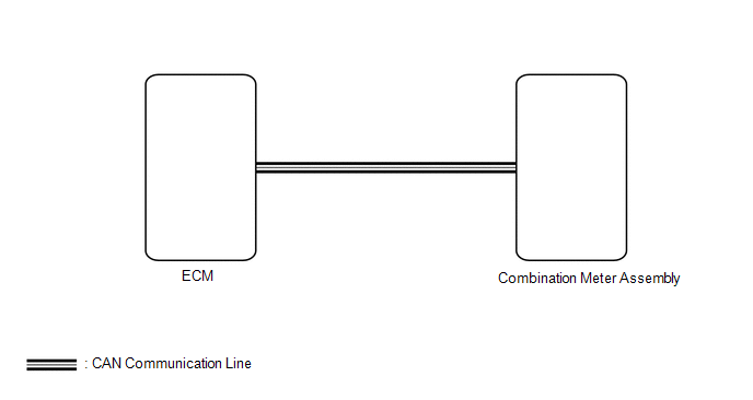
In this circuit, the combination meter assembly receives engine coolant temperature signals from the ECM via the CAN communication system. The combination meter assembly displays the engine coolant temperature that is calculated based on the data received from the ECM.
WIRING DIAGRAM
CAUTION / NOTICE / HINT
NOTICE:
- When replacing the combination meter assembly, make sure to replace it with a new one.
-
If there is an open or short in the engine coolant temperature sensor circuit, the ECM stores DTCs. Troubleshoot the SFI system.
Click here
.gif)
PROCEDURE
| 1. | CHECK FOR DTC (CAN COMMUNICATION SYSTEM) |
(a) Check for DTCs.
Click here
OK:
No DTCs are output.
| NG | .gif) | GO TO CAN COMMUNICATION SYSTEM |
|
.gif)
| 2. | CHECK FOR DTC (SFI SYSTEM) |
(a) Check for DTCs.
w/ EGR System: Click here
w/o EGR System: Click here
Powertrain > Engine and ECT > Trouble CodesOK:
No DTCs are output.
| NG | | GO TO SFI SYSTEM |
|
| 3. | PERFORM ACTIVE TEST USING TECHSTREAM (WATER TEMPERATURE METER OPERATION) |
(a) Using the Techstream, perform the Active Test.
Click here
| Tester Display | Measurement Item | Control Range | Diagnostic Note |
|---|---|---|---|
| Water Temperature Meter Operation | Engine coolant temperature receiver gauge | OFF, LOW, NORMAL, HIGH | - |
| Tester Display |
|---|
| Water Temperature Meter Operation |
OK:
Engine coolant temperature receiver gauge indication is normal.
| NG | | REPLACE COMBINATION METER ASSEMBLY |
|
| 4. | READ VALUE USING TECHSTREAM (COOLANT TEMP, COOLANT TEMPERATURE) |
(a) Using the Techstream, read the Data List.
Click here
| Tester Display | Measurement Item | Range | Normal Condition | Diagnostic Note |
|---|---|---|---|---|
| Coolant Temp | Engine coolant temperature | Min.: -40°C (-40°F), Max: 215°C (419°F) | 75 to 100°C (167 to 212°F): After warming up the engine | - |
| Tester Display | Measurement Item | Range | Normal Condition | Diagnostic Note |
|---|---|---|---|---|
| Coolant Temperature | Engine coolant temperature | Min.: 0°C (0°F), Max.: 127.5°C (261.5°F) | 75 to 100°C (167 to 212°F): After warming up the engine | - |
| Tester Display |
|---|
| Coolant Temp |
| Tester Display |
|---|
| Coolant Temperature |
HINT:
- When the Data List values of the ECUs match, an internal malfunction of the ECM is suspected.
- When the Data List values of the ECUs do not match, a signal output error of the ECM or an internal malfunction of the combination meter assembly is suspected.
OK:
The Data List values of the ECUs do not match.
| NG | | REPLACE ECM |
|
| 5. | CHECK COMBINATION METER ASSEMBLY |
(a) Replace the combination meter assembly.
Click here
(b) Check that the operation of the engine coolant temperature receiver gauge returns to normal.
OK:
The operation of the engine coolant temperature receiver gauge returns to normal.
| OK | | END (COMBINATION METER ASSEMBLY IS DEFECTIVE) |
| NG | | REPLACE ECM |
READ NEXT:
 Hybrid System Indicator Malfunction
DESCRIPTION A hybrid system indicator has been used on this vehicle. In this circuit, the combination meter assembly receives the eco-zone indicator level signal from the hybrid vehicle control ECU vi
Odo/Trip Switch Malfunction
DESCRIPTION The ODO/TRIP display of the combination meter changes each time the trip switch is pressed. WIRING DIAGRAM CAUTION / NOTICE / HINT NOTICE: When replacing the combination meter assembly, m
Operating Light Control Rheostat does not Change Light Brightness
DESCRIPTION The combination meter assembly receives signals from this circuit to adjust the illumination of the combination meter assembly. The combination meter assembly sets the illumination level b
SEE MORE:
Replacement
REPLACEMENT PROCEDURE 1. REPLACE INTAKE VALVE GUIDE BUSH (a) Heat the cylinder head sub-assembly to approximately 80 to 100°C (176 to 212°F). (b) Place the cylinder head sub-assembly on wooden blocks. (c) Using SST and a hammer, tap out the intake valve guide bush. SST: 09201-01055 SST: 09950-7
Removal
REMOVAL CAUTION / NOTICE / HINT NOTICE: While the auxiliary battery is connected, even if the power switch is off, the brake control system activates when the brake pedal is depressed or any door courtesy switch turns on. Therefore, when servicing the brake system components, do not operate the brak
