Lexus NX: Operating Light Control Rheostat does not Change Light Brightness
DESCRIPTION
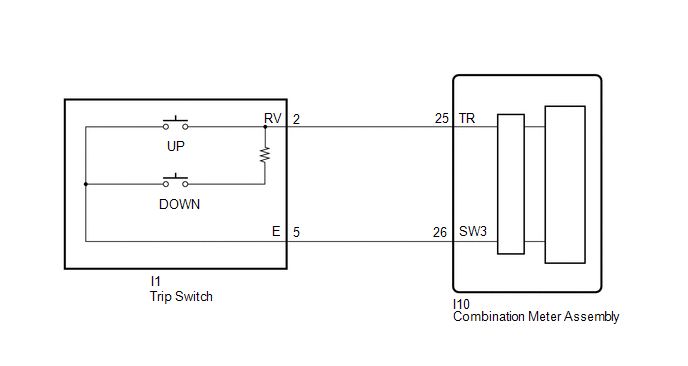
The combination meter assembly receives signals from this circuit to adjust the illumination of the combination meter assembly. The combination meter assembly sets the illumination level based on the user operation of the light control rheostat switch in the trip switch.
WIRING DIAGRAM
CAUTION / NOTICE / HINT
NOTICE:
When replacing the combination meter assembly, make sure to replace it with a new one.
HINT:
- The meter illumination level can be adjusted by pressing the light control rheostat switch.
- The meter illumination dims when the taillights are turned on.
- Setting the meter illumination to maximum brightness cancels the above dimming of the meter illumination.
PROCEDURE
| 1. | READ VALUE USING TECHSTREAM (LIGHT CONTROL UP SWITCH, LIGHT CONTROL DOWN SWITCH) |
(a) Using the Techstream, read the Data List.
Click here .gif)
| Tester Display | Measurement Item | Range | Normal Condition | Diagnostic Note |
|---|---|---|---|---|
| Light Control Up Switch | Light control rheostat up switch | OFF or ON | OFF: Light control rheostat up switch released ON: Light control rheostat up switch pressed | - |
| Light Control Down Switch | Light control rheostat down switch | OFF or ON | OFF: Light control rheostat down switch released ON: Light control rheostat down switch pressed | - |
| Tester Display |
|---|
| Light Control Up Switch |
| Light Control Down Switch |
OK:
Light control rheostat up or down switch condition displayed on the Techstream changes with the actual switch operation.
| OK | .gif) | REPLACE COMBINATION METER ASSEMBLY |
|
.gif)
| 2. | INSPECT TRIP SWITCH |
(a) Remove the trip switch.
Click here
(b) Inspect the trip switch.
Click here
| NG | | REPLACE TRIP SWITCH |
|
| 3. | CHECK HARNESS AND CONNECTOR (COMBINATION METER ASSEMBLY - TRIP SWITCH) |
(a) Disconnect the I10 combination meter assembly connector.
(b) Disconnect the I1 trip switch connector.
(c) Measure the resistance according to the value(s) in the table below.
Standard Resistance:
| Tester Connection | Condition | Specified Condition |
|---|---|---|
| I10-25 (TR) - I1-2 (RV) | Always | Below 1 Ω |
| I10-26 (SW3) - I1-5 (E) | Always | Below 1 Ω |
| I10-25 (TR) or I1-2 (RV) - Body ground | Always | 10 kΩ or higher |
| I10-26 (SW3) or I1-5 (E) - Body ground | Always | 10 kΩ or higher |
| OK | | REPLACE COMBINATION METER ASSEMBLY |
| NG | | REPAIR OR REPLACE HARNESS OR CONNECTOR |
READ NEXT:
 Speed Signal Circuit
DESCRIPTION The combination meter assembly receives the vehicle speed signal from this circuit. The wheel speed sensors produce an output that varies according to the vehicle speed. The wheel speed se
Components
COMPONENTS ILLUSTRATION *1 INSTRUMENT SIDE PANEL LH *2 NO. 1 INSTRUMENT PANEL SAFETY PAD SUB-ASSEMBLY *3 TRIP SWITCH - -
SEE MORE:
Drive Motor "B" Control Module (P0A1C-713)
DESCRIPTION The MG ECU, which is built into the inverter with converter assembly, monitors its internal operation and will store DTCs if the system is malfunctioning. If any of the following DTCs are output, replace the inverter with converter assembly. DTC No. Detection Item DTC Detection Co
Components
COMPONENTS ILLUSTRATION *A w/ Woofer *B w/o Woofer *1 BACK DOOR CENTER GARNISH *2 BACK DOOR LOCK COVER *3 BACK DOOR SIDE GARNISH LH *4 BACK DOOR SIDE GARNISH RH *5 BACK DOOR TRIM BASE *6 BACK DOOR TRIM BOARD ASSEMBLY *7 MULTIPLEX NETWORK DOOR ECU *8
