Lexus NX: Entry Exterior Alarm and Answer-back Buzzer do not Sound
DESCRIPTION
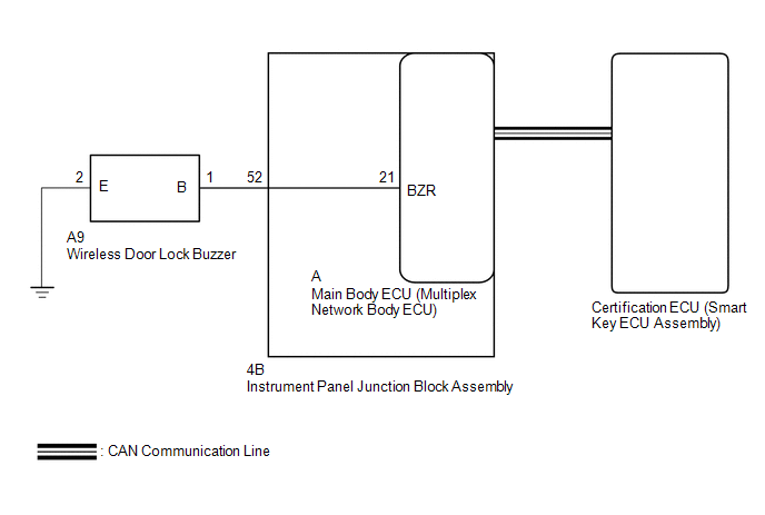
The smart access system with push-button start (for Entry Function) uses the wireless door lock buzzer to perform various vehicle exterior warnings. When the conditions of each warning are met, the certification ECU (smart key ECU assembly) sends a buzzer activation request signal to the main body ECU (multiplex network body ECU) via CAN communication and the buzzer sounds.
WIRING DIAGRAM
CAUTION / NOTICE / HINT
NOTICE:
-
The smart access system with push-button start (for Entry Function) uses the LIN communication system and CAN communication system. Inspect the communication function by following How to Proceed with Troubleshooting. Troubleshoot the smart access system with push-button start (for Entry Function) after confirming that the communication systems are functioning properly.
Click here
.gif)
- When using the Techstream with the power switch off, connect the Techstream to the DLC3 and turn a courtesy light switch on and off at intervals of 1.5 seconds or less until communication between the Techstream and the vehicle begins. Then select the vehicle type under manual mode and enter the following menus: Body Electrical / Smart Access. While using the Techstream, periodically turn a courtesy light switch on and off at intervals of 1.5 seconds or less to maintain communication between the Techstream and the vehicle.
-
Before replacing the certification ECU (smart key ECU assembly) or main body ECU (multiplex network body ECU), refer to smart access system with push-button start (for Entry Function) Precaution.
Click here
- After repair, confirm that no DTCs are output by performing "DTC Output Confirmation Operation".
PROCEDURE
| 1. | CHECK CUSTOMIZE SETTING (WIRELESS BUZZER RESP) |
(a) Connect the Techstream to the DLC3.
(b) Turn the power switch on (IG).
(c) Turn the Techstream on.
(d) Enter the following menus: Customize Setting / Wireless Door Lock.
Wireless Door Lock| Tester Display | Description | Default | Setting | ECU |
|---|---|---|---|---|
| Wireless Buzzer Resp | Wireless buzzer response | ON | 0:OFF,1:ON | Main body ECU (multiplex network body ECU) |
| Result | Proceed to |
|---|---|
| "ON" is displayed | A |
| "OFF" is displayed | B |
| B | .gif) | PERFORM CUSTOMIZE SETTING |
|
.gif)
| 2. | CHECK WIRELESS DOOR LOCK CONTROL SYSTEM |
(a) Check that the wireless door lock functions operate normally.
Click here
| Result | Proceed to |
|---|---|
| Wireless door lock function operates normally | A |
| Wireless door lock function does not operate normally | B |
| B | | GO TO PROBLEM SYMPTOMS TABLE |
|
| 3. | READ VALUE USING TECHSTREAM (EACH UNLOCK DETECTION SWITCH) |
(a) Connect the Techstream to the DLC3.
(b) Turn the power switch on (IG).
(c) Turn the Techstream on.
(d) Enter the following menus: Body Electrical / Main Body / Data List.
(e) Read the Data List according to the display on the Techstream.
Body Electrical > Main Body > Data List| Tester Display | Measurement Item | Range | Normal Condition | Diagnostic Note |
|---|---|---|---|---|
| FR Door Lock Pos | Front door RH unlock detection switch signal | UNLOCK or LOCK | UNLOCK: Front door RH unlocked LOCK: Front door RH locked | - |
| FL Door Lock Pos | Front door LH unlock detection switch signal | UNLOCK or LOCK | UNLOCK: Front door LH unlocked LOCK: Front door LH locked | - |
| RR-Door Lock Pos SW | Rear door RH unlock detection switch signal | ON or OFF | ON: Rear door RH unlocked OFF: Rear door RH locked | - |
| RL-Door Lock Pos SW | Rear door LH unlock detection switch signal | ON or OFF | ON: Rear door LH unlocked OFF: Rear door LH locked | - |
| Tester Display |
|---|
| FR Door Lock Pos |
| FL Door Lock Pos |
| RR-Door Lock Pos SW |
| RL-Door Lock Pos SW |
OK:
The Techstream display changes correctly in response to the lock/unlock operation.
| NG | | GO TO LIGHTING SYSTEM (Proceed to Door Unlock Detection Switch Circuit) |
|
| 4. | PERFORM ACTIVE TEST USING TECHSTREAM (WIRELESS BUZZER) |
(a) Connect the Techstream to the DLC3.
(b) Turn the power switch on (IG).
(c) Turn the Techstream on.
(d) Enter the following menus: Body Electrical / Main Body / Active Test.
(e) Perform Active Test according to the display on the Techstream.
Body Electrical > Main Body > Active Test| Tester Display | Measurement Item | Control Range | Diagnostic Note |
|---|---|---|---|
| Wireless Buzzer | Wireless door lock buzzer | OFF/ON | - |
| Tester Display |
|---|
| Wireless Buzzer |
| Result | Proceed to |
|---|---|
| Wireless buzzer does not sound | A |
| Wireless buzzer sounds | B |
| B | | REPLACE CERTIFICATION ECU (SMART KEY ECU ASSEMBLY) |
|
| 5. | CHECK WIRELESS DOOR LOCK BUZZER |
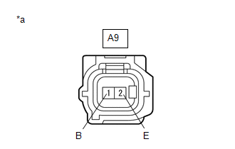
(a) Disconnect the A9 wireless door lock buzzer connector.
(b) Perform the Active Test using the Techstream and sound the wireless door lock buzzer.
Body Electrical > Main Body > Active Test| Tester Display | Measurement Item | Control Range | Diagnostic Note |
|---|---|---|---|
| Wireless Buzzer | Wireless door lock buzzer | OFF/ON | - |
| Tester Display |
|---|
| Wireless Buzzer |
| (c) While performing the Active Test, measure the voltage between the terminals of the wireless door lock buzzer. Standard Voltage:
|
|
| OK | | REPLACE WIRELESS DOOR LOCK BUZZER |
|
| 6. | CHECK HARNESS AND CONNECTOR (WIRELESS DOOR LOCK BUZZER - MAIN BODY ECU (MULTIPLEX NETWORK BODY ECU) AND BODY GROUND) |
(a) Remove the main body ECU (multiplex network body ECU) from the instrument panel junction block assembly.
Click here
(b) Disconnect the A9 wireless door lock buzzer connector.
(c) Reconnect the 4B instrument panel junction block assembly connector.
(d) Measure the resistance according to the value(s) in the table below.
Standard Resistance:
| Tester Connection | Condition | Specified Condition |
|---|---|---|
| A9-1 (B) - A-21 (BZR) | Always | Below 1 Ω |
| A9-2 (E) - Body ground | Always | Below 1 Ω |
| A9-1 (B) or A-21 (BZR) - Body ground | Always | 10 kΩ or higher |
| OK | | REPLACE MAIN BODY ECU (MULTIPLEX NETWORK BODY ECU) |
|
| 7. | CHECK HARNESS AND CONNECTOR (WIRELESS DOOR LOCK BUZZER - INSTRUMENT PANEL JUNCTION BLOCK ASSEMBLY) |
(a) Disconnect the 4B instrument panel junction block assembly connector.
(b) Disconnect the A9 wireless door lock buzzer connector.
(c) Measure the resistance according to the value(s) in the table below.
Standard Resistance:
| Tester Connection | Condition | Specified Condition |
|---|---|---|
| A9-1 (B) - 4B-52 (BZR) | Always | Below 1 Ω |
| A9-1 (B) or 4B-52 (BZR) - Body ground | Always | 10 kΩ or higher |
| OK | | REPLACE INSTRUMENT PANEL JUNCTION BLOCK ASSEMBLY |
| NG | | REPAIR OR REPLACE HARNESS OR CONNECTOR |
READ NEXT:
 Precaution
PRECAUTION PRECAUTION FOR DISCONNECTING CABLE FROM NEGATIVE AUXILIARY BATTERY TERMINAL NOTICE:
After the power switch is turned off, there may be a waiting time before disconnecting the negative (-
Parts Location
PARTS LOCATION ILLUSTRATION *1 NO. 1 ENGINE ROOM RELAY BLOCK - IG2-MAIN RELAY *2 NO. 2 ENGINE ROOM RELAY BLOCK - IG1 RELAY *3 SKID CONTROL ECU (BRAKE BOOSTER WITH MASTER CYLINDER ASSEM
SEE MORE:
Front Right Sensor Malfunction (C1AE4)
DESCRIPTION The front corner ultrasonic sensor (FR sensor) is installed to the front bumper. The clearance warning ECU assembly detects obstacles based on signals received from the front corner ultrasonic sensor (FR sensor). If the front corner ultrasonic sensor (FR sensor) has an open circuit or ot
Vanity Light Bulb
ReplacementREPLACEMENT CAUTION / NOTICE / HINT HINT:
Use the same procedure for the RH and LH sides.
The procedure listed below is for the LH side.
PROCEDURE 1. DISCONNECT VANITY LIGHT ASSEMBLY (a) Using a screwdriver, detach the claw and disconnect the vanity light assembly. HINT: Tape
