Lexus NX: Components
COMPONENTS
ILLUSTRATION
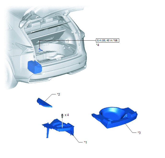
| *1 | DECK FLOOR BOX LH | *2 | NO. 3 DECK BOARD SUB-ASSEMBLY |
| *3 | REAR DECK FLOOR BOX | *4 | NEGATIVE AUXILIARY BATTERY TERMINAL |
.png) | N*m (kgf*cm, ft.*lbf): Specified torque | - | - |
ILLUSTRATION
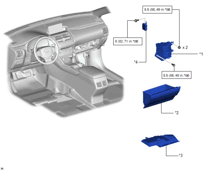
| *1 | ECU INTEGRATION BOX RH | *2 | GLOVE COMPARTMENT DOOR ASSEMBLY |
| *3 | NO. 2 INSTRUMENT PANEL UNDER COVER SUB-ASSEMBLY | *4 | VEHICLE APPROACHING SPEAKER CONTROLLER |
| | N*m (kgf*cm, ft.*lbf): Specified torque | - | - |
READ NEXT:
 Removal
REMOVAL PROCEDURE 1. PRECAUTION CAUTION: Be sure to read Precoution thoroughly before serving. Click here NOTICE: After the power switch is turned off, there may be a waiting time before disconnecti
Installation
INSTALLATION PROCEDURE 1. INSTALL VEHICLE APPROACHING SPEAKER CONTROLLER (a) Connect the connector. (b) Attach the hook to install the vehicle approaching speaker controller. NOTICE:
When installin
SEE MORE:
Components
COMPONENTS ILLUSTRATION *1 HEADLIGHT ASSEMBLY LH - - N*m (kgf*cm, ft.*lbf): Specified torque - - ILLUSTRATION *1 HEADLIGHT ECU SUB-ASSEMBLY LH *2 HEADLIGHT GASKET ● Non-reusable part - - ILLUSTRATION *1 LOWER HEADLIGHT PROTECTOR RETAINER LH *2
Open or Short Circuit in Release Switch Circuit (C13A4,C13AC)
DESCRIPTION When the electric parking brake switch (integration control and panel assembly) is pushed to the release side, a release request signal is output to the parking brake ECU assembly. DTC No. Detection Item DTC Detection Condition Trouble Area Memory Note C13A4 Open or Sh
© 2016-2026 Copyright www.lexunx.com
