Lexus NX: Front Airbag Sensor Lost Communication (RH) (B1612,B1613)
DESCRIPTION
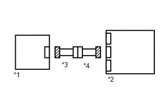
The front airbag sensor RH circuit consists of the airbag ECU assembly and front airbag sensor RH.
The front airbag sensor RH detects impacts to the vehicle and sends signals to the airbag ECU assembly to determine if the airbag should be deployed.
DTC B1612 or B1613 is stored when a malfunction is detected in the front airbag sensor RH circuit.
| DTC No. | Detection Item | DTC Detection Condition | Trouble Area |
|---|---|---|---|
| B1612 | Front Airbag Sensor Lost Communication (RH) | One of the following conditions is met:
|
|
| B1613 | Front Airbag Sensor Initialization Error (RH) | One of the following conditions is met:
|
|
WIRING DIAGRAM
.png)
CAUTION / NOTICE / HINT
NOTICE:
-
After the power switch is turned off, there may be a waiting time before disconnecting the negative (-) auxiliary battery terminal.
Click here
.gif)
-
When disconnecting and reconnecting the auxiliary battery
Click here
HINT:
When disconnecting and reconnecting the auxiliary battery, there is an automatic learning function that completes learning when the respective system is used.
Click here
-
After replacing the airbag ECU assembly, refer to initialization.
Click here
PROCEDURE
| 1. | CHECK CONNECTION OF CONNECTORS |
(a) Turn the power switch off.
(b) Disconnect the cable from the negative (-) auxiliary battery terminal, and wait for at least 90 seconds.
(c) Check that the connectors are properly connected to the airbag ECU assembly and front airbag sensor RH.
| The connectors are not properly connected | .gif) | CONNECT CONNECTORS PROPERLY |
|
.gif)
| 2. | CHECK CONNECTORS |
(a) Disconnect the connectors from the airbag ECU assembly and front airbag sensor RH.
| (b) Check that the connectors (on the airbag ECU assembly side and front airbag sensor RH side) are not damaged. |
|
| The connectors are deformed or damaged | | REPLACE INSTRUMENT PANEL WIRE OR ENGINE ROOM MAIN WIRE |
|
| 3. | CHECK FRONT AIRBAG SENSOR RH CIRCUIT |
(a) Connect the cable to the negative (-) auxiliary battery terminal, and wait for at least 2 seconds.
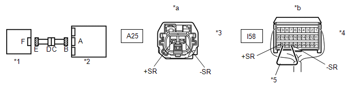
| *1 | Front Airbag Sensor RH | *2 | Airbag ECU Assembly |
| *3 | Connector E | *4 | Connector B |
| *5 | Service Wire | - | - |
| *a | Rear view of wire harness connector (to Front Airbag Sensor RH) | *b | Rear view of wire harness connector (to Airbag ECU Assembly) |
(b) Turn the power switch on (IG).
(c) Measure the voltage according to the value(s) in the table below.
Standard Voltage:
| Tester Connection | Switch Condition | Specified Condition |
|---|---|---|
| A25-2 (+SR) - Body ground | Power switch on (IG) | Below 1 V |
| A25-1 (-SR) - Body ground | Power switch on (IG) | Below 1 V |
(d) Turn the power switch off.
(e) Disconnect the cable from the negative (-) auxiliary battery terminal, and wait for at least 90 seconds.
(f) Using a service wire, connect terminals 29 (+SR) and 27 (-SR) of connector B.
NOTICE:
Do not forcibly insert the service wire into the terminals of the connector when connecting a service wire.
(g) Measure the resistance according to the value(s) in the table below.
Standard Resistance:
| Tester Connection | Condition | Specified Condition |
|---|---|---|
| A25-2 (+SR) - A25-1 (-SR) | Always | Below 1 Ω |
(h) Disconnect the service wire from connector B.
(i) Measure the resistance according to the value(s) in the table below.
Standard Resistance:
| Tester Connection | Condition | Specified Condition |
|---|---|---|
| A25-2 (+SR) - A25-1 (-SR) | Always | 1 MΩ or higher |
| A25-2 (+SR) - Body ground | Always | 1 MΩ or higher |
| A25-1 (-SR) - Body ground | Always | 1 MΩ or higher |
| NG | | GO TO STEP 5 |
|
| 4. | CHECK FRONT AIRBAG SENSOR RH |
| (a) Connect the connectors to the airbag ECU assembly. |
|
(b) Interchange the front airbag sensor RH with LH and connect the connectors to them.
(c) Connect the cable to the negative (-) auxiliary battery terminal, and wait for at least 2 seconds.
(d) Turn the power switch on (IG), and wait for at least 60 seconds.
(e) Clear the DTCs stored in memory.
Click here
(f) Turn the power switch off.
(g) Turn the power switch on (IG), and wait for at least 60 seconds.
(h) Check for DTCs.
Click here
HINT:
Codes other than DTC B1612, B1613, B1617 and B1618 may be output at this time, but they are not related to this check.
(i) Turn the power switch off.
(j) Disconnect the cable from the negative (-) auxiliary battery terminal, and wait for at least 90 seconds.
(k) Return the front airbag sensor LH and RH to their original positions and connect the connectors to them.
| DTC B1612 or B1613 is output | | REPLACE AIRBAG ECU ASSEMBLY |
| DTC B1617 or B1618 is output | | REPLACE FRONT AIRBAG SENSOR RH |
| DTC B1612, B1613, B1617 and B1618 are not output | | USE SIMULATION METHOD TO CHECK |
| 5. | CHECK INSTRUMENT PANEL WIRE |
(a) Disconnect the instrument panel wire connector from the engine room main wire.
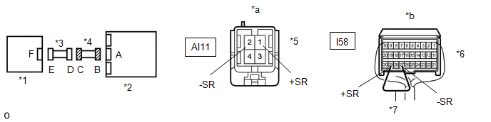
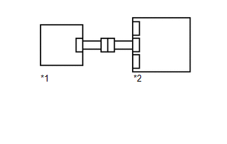
| *1 | Front Airbag Sensor RH | *2 | Airbag ECU Assembly |
| *3 | Engine Room Main Wire | *4 | Instrument Panel Wire |
| *5 | Connector C | *6 | Connector B |
| *7 | Service Wire | - | - |
| *a | Front view of wire harness connector (to Engine Room Main Wire) | *b | Rear view of wire harness connector (to Airbag ECU Assembly) |
(b) Connect the cable to the negative (-) auxiliary battery terminal, and wait for at least 2 seconds.
(c) Turn the power switch on (IG).
(d) Measure the voltage according to the value(s) in the table below.
Standard Voltage:
| Tester Connection | Switch Condition | Specified Condition |
|---|---|---|
| AI11-1 (+SR) - Body ground | Power switch on (IG) | Below 1 V |
| AI11-2 (-SR) - Body ground | Power switch on (IG) | Below 1 V |
(e) Turn the power switch off.
(f) Disconnect the cable from the negative (-) auxiliary battery terminal, and wait for at least 90 seconds.
(g) Using a service wire, connect terminals 29 (+SR) and 27 (-SR) of connector B.
NOTICE:
Do not forcibly insert the service wire into the terminals of the connector when connecting a service wire.
(h) Measure the resistance according to the value(s) in the table below.
Standard Resistance:
| Tester Connection | Condition | Specified Condition |
|---|---|---|
| AI11-1 (+SR) - AI11-2 (-SR) | Always | Below 1 Ω |
(i) Disconnect the service wire from connector B.
(j) Measure the resistance according to the value(s) in the table below.
Standard Resistance:
| Tester Connection | Condition | Specified Condition |
|---|---|---|
| AI11-1 (+SR) - AI11-2 (-SR) | Always | 1 MΩ or higher |
| AI11-1 (+SR) - Body ground | Always | 1 MΩ or higher |
| AI11-2 (-SR) - Body ground | Always | 1 MΩ or higher |
| OK | | REPLACE ENGINE ROOM MAIN WIRE |
| NG | | REPLACE INSTRUMENT PANEL WIRE |
READ NEXT:
 Front Airbag Sensor (LH) (B1615)
DESCRIPTION The front airbag sensor LH consists of a diagnostic circuit and frontal deceleration sensor, etc. If the airbag ECU assembly receives signals from the frontal deceleration sensor, it deter
Front Airbag Sensor Lost Communication (LH) (B1617,B1618)
DESCRIPTION The front airbag sensor LH circuit consists of the airbag ECU assembly and front airbag sensor LH. The front airbag sensor LH detects impacts to the vehicle and sends signals to the airbag
Curtain Shield Airbag Sensor (RH) (B1630,B1632,B1635,B1637)
DESCRIPTION The side airbag sensor assembly LH or RH consists of a lateral deceleration sensor, etc. If the airbag ECU assembly receives signals from the lateral deceleration sensor, it determines whe
SEE MORE:
Disc cannot be Inserted or is Ejected Right After Insertion
CAUTION / NOTICE / HINT NOTICE: When replacing the radio receiver assembly, always replace it with a new one. If a radio receiver assembly which was installed to another vehicle is used, the following may occur:
A communication malfunction DTC may be stored.
The radio receiver assembly may not
Inspection
INSPECTION PROCEDURE 1. INSPECT LICENSE PLATE LIGHT ASSEMBLY LH (a) Apply auxiliary battery voltage to the connector and check the light illumination condition. OK: Condition Specified Condition Auxiliary battery positive (+) → Y4-1 (B) Auxiliary battery negative (-) → Y4-2 (E) Li
