Lexus NX: Curtain Shield Airbag Sensor (RH) (B1630,B1632,B1635,B1637)
DESCRIPTION
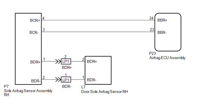
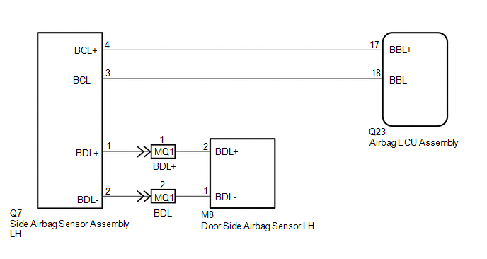
The side airbag sensor assembly LH or RH consists of a lateral deceleration sensor, etc.
If the airbag ECU assembly receives signals from the lateral deceleration sensor, it determines whether the SRS should be activated.
DTC B1630, B1632, B1635 or B1637 is stored when a malfunction is detected in the side airbag sensor assembly LH or RH circuit.
| DTC No. | Detection Item | DTC Detection Condition | Trouble Area |
|---|---|---|---|
| B1630 | Curtain Shield Airbag Sensor (RH) | Either condition is met:
|
|
| B1632 | Curtain Shield Airbag Sensor Lost Communication (RH) | Either condition is met:
|
|
| B1635 | Curtain Shield Airbag Sensor (LH) | Either condition is met:
|
|
| B1637 | Curtain Shield Airbag Sensor Lost Communication (LH) | Either condition is met:
|
|
WIRING DIAGRAM
CAUTION / NOTICE / HINT
NOTICE:
-
After the power switch is turned off, there may be a waiting time before disconnecting the negative (-) auxiliary battery terminal.
Click here
.gif)
-
When disconnecting and reconnecting the auxiliary battery
Click here
HINT:
When disconnecting and reconnecting the auxiliary battery function that completes learning when the respective system is used.
Click here
-
After replacing the airbag ECU assembly, refer to initialization.
Click here
PROCEDURE
| 1. | CHECK DTC |
(a) Turn the power switch on (IG), and wait for at least 60 seconds.
(b) Clear the DTCs stored in memory.
Click here
(c) Turn the power switch off.
(d) Turn the power switch on (IG), and wait for at least 60 seconds.
(e) Check for DTCs.
Click here
HINT:
Codes other than DTC B1630, B1632, B1635 and B1637 may be output at this time, but they are not related to this check.
| DTC B1630 or B1632 is output | .gif) | GO TO STEP 3 |
| DTC B1630, B1632, B1635 and B1637 are not output | | USE SIMULATION METHOD TO CHECK |
|
.gif)
| 2. | CHECK SIDE AIRBAG SENSOR ASSEMBLY LH |
| (a) Turn the power switch off. |
|
(b) Disconnect the cable from the negative (-) auxiliary battery terminal, and wait for at least 90 seconds.
(c) Interchange the side airbag sensor assembly LH with RH and connect the connectors to them.
(d) Connect the cable to the negative (-) auxiliary battery terminal, and wait for at least 2 seconds.
(e) Turn the power switch on (IG), and wait for at least 60 seconds.
(f) Clear the DTCs stored in memory.
Click here
(g) Turn the power switch off.
(h) Turn the power switch on (IG), and wait for at least 60 seconds.
(i) Check for DTCs.
Click here
HINT:
Codes other than DTC B1630, B1632, B1635 and B1637 may be output at this time, but they are not related to this check.
(j) Turn the power switch off.
(k) Disconnect the cable from the negative (-) auxiliary battery terminal, and wait for at least 90 seconds.
(l) Return the side airbag sensor assembly RH and LH to their original positions and connect the connectors to them.
| DTC B1630 or B1632 is output | | REPLACE SIDE AIRBAG SENSOR ASSEMBLY LH |
| DTC B1635 or B1637 is output | | REPLACE AIRBAG ECU ASSEMBLY |
| DTC B1630, B1632, B1635 and B1637 are not output | | USE SIMULATION METHOD TO CHECK |
| 3. | CHECK SIDE AIRBAG SENSOR ASSEMBLY RH |
| (a) Turn the power switch off. |
|
(b) Disconnect the cable from the negative (-) auxiliary battery terminal, and wait for at least 90 seconds.
(c) Interchange the side airbag sensor assembly RH with LH and connect the connectors to them.
(d) Connect the cable to the negative (-) auxiliary battery terminal, and wait for at least 2 seconds.
(e) Turn the power switch on (IG), and wait for at least 60 seconds.
(f) Clear the DTCs stored in memory.
Click here
(g) Turn the power switch off.
(h) Turn the power switch on (IG), and wait for at least 60 seconds.
(i) Check for DTCs.
Click here
HINT:
Codes other than DTC B1630, B1632, B1635 and B1637 may be output at this time, but they are not related to this check.
(j) Turn the power switch off.
(k) Disconnect the cable from the negative (-) auxiliary battery terminal, and wait for at least 90 seconds.
(l) Return the side airbag sensor assembly LH and RH to their original positions and connect the connectors to them.
| DTC B1635 or B1637 is output | | REPLACE SIDE AIRBAG SENSOR ASSEMBLY RH |
| DTC B1630 or B1632 is output | | REPLACE AIRBAG ECU ASSEMBLY |
| DTC B1630, B1632, B1635 and B1637 are not output | | USE SIMULATION METHOD TO CHECK |
READ NEXT:
 Side Satellite Sensor Bus Lost Communication (RH) (B1642,B1643,B1647,B1648)
DESCRIPTION The circuit for the side collision sensor LH or RH is composed of the airbag ECU assembly, side airbag sensor assembly LH or RH and door side airbag sensor LH or RH. The door side airbag s
Occupant Classification System Malfunction (B1650)
DESCRIPTION The occupant classification system circuit consists of the airbag ECU assembly and occupant detection ECU. If the airbag ECU assembly receives signals from the occupant detection ECU, it d
Driver Side Seat Position Sensor (B1653)
DESCRIPTION The seat position airbag sensor circuit consists of the airbag ECU assembly and seat position airbag sensor. DTC B1653 is stored when a malfunction is detected in the seat position airbag
SEE MORE:
Components
COMPONENTS ILLUSTRATION *1 COOLER EXPANSION VALVE *2 NO. 1 COOLER EVAPORATOR SUB-ASSEMBLY *3 NO. 1 COOLER THERMISTOR *4 UPPER HEATER CASE *5 LOWER HEATER CASE *6 O-RING N*m (kgf*cm, ft.*lbf): Specified torque ● Non-reusable part Compressor oil ND-OIL
System Description
SYSTEM DESCRIPTION WASHER-LINKED FUNCTION (a) This system operates the front wipers at low speed immediately after spraying a jet of washer fluid when the front washer switch is turned on for 0.3 seconds or more. The system operates the front wipers at low speed for approximately 2.2 seconds and the
