Lexus NX: Front Camera Current Malfunction (C1682)
DESCRIPTION
This DTC is stored if the parking assist ECU judges as a result of its self check that there is a problem with the current supplied from the front television camera assembly connected to the parking assist ECU.
| DTC No. | Detection Item | DTC Detection Condition | Trouble Area |
|---|---|---|---|
| C1682 | Front Camera Current Malfunction | Open or short in the front television camera signal circuit |
|
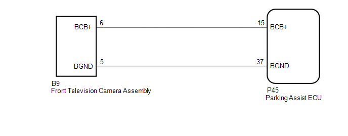
WIRING DIAGRAM
CAUTION / NOTICE / HINT
NOTICE:
-
When "!" mark is displayed on the multi-display assembly after the cable is disconnected from the negative (-) auxiliary battery terminal, correct the steering angle neutral point.
Click here
.gif)
-
Depending on the parts that are replaced or operations that are performed during vehicle inspection or maintenance, calibration of other systems as well as panoramic view monitor system may be needed.
Click here
PROCEDURE
| 1. | CHECK HARNESS AND CONNECTOR (PARKING ASSIST ECU - FRONT TELEVISION CAMERA ASSEMBLY) |
(a) Disconnect the P45 parking assist ECU connector.
(b) Disconnect the B9 front television camera assembly connector.
(c) Measure the resistance according to the value(s) in the table below.
Standard Resistance:
| Tester Connection | Condition | Specified Condition |
|---|---|---|
| P45-15 (BCB+) - B9-6 (BCB+) | Always | Below 1 Ω |
| P45-37 (BGND) - B9-5 (BGND) | Always | Below 1 Ω |
| P45-15 (BCB+) or B9-6 (BCB+) - Body ground | Always | 10 kΩ or higher |
| P45-37 (BGND) or B9-5 (BGND) - Body ground | Always | 10 kΩ or higher |
| NG | .gif) | REPAIR OR REPLACE HARNESS OR CONNECTOR |
|
.gif)
| 2. | CHECK PARKING ASSIST ECU (BCB+, BGND) |
| (a) Disconnect the front television camera assembly connector. |
|
.png)
(b) Measure the resistance according to the value(s) in the table below.
Standard Resistance:
| Tester Connection | Condition | Specified Condition |
|---|---|---|
| P45-37 (BGND) - Body ground | Always | Below 1 Ω |
(c) Measure the voltage according to the value(s) in the table below.
Standard Voltage:
| Tester Connection | Switch Condition | Specified Condition |
|---|---|---|
| P45-15 (BCB+) - P45-37 (BGND) | Power switch on (IG) | 5.5 to 7.05 V |
| P45-15 (BCB+) - P45-37 (BGND) | Power switch off | Below 1 V |
| OK | | REPLACE FRONT TELEVISION CAMERA ASSEMBLY |
| NG | | REPLACE PARKING ASSIST ECU |
READ NEXT:
 Side Camera Feedback Malfunction (C1683)
DESCRIPTION This DTC is stored if the parking assist ECU judges as a result of its self check that a synchronization problem is occurring in the image signal sent from the passenger side television ca
Side Camera Current Malfunction (C1684)
DESCRIPTION This DTC is stored if the parking assist ECU judges as a result of its self check that a synchronization problem is occurring in the image signal sent from the passenger side television ca
Driver Side Camera Video Sync Signal Malfunction (C1686)
DESCRIPTION This DTC is stored if the parking assist ECU judges as a result of its self check that a synchronization problem is occurring in the image signal sent from the driver side television camer
SEE MORE:
Initialization
INITIALIZATION Inspection After Repair Perform learning value reset and idle learning after replacing or servicing parts related to engine operation. Details on procedures required are indicated by an asterisk and a number, and are explained in detail following the table. Part Replaced Engine O
Knock Sensor 1 Circuit Low Input (Bank 1 or Single Sensor) (P0327,P0328)
DESCRIPTION A flat type knock control sensor (non-resonant type) has a structure that can detect vibration between approximately 5 kHz and 23 kHz. The knock control sensors are fitted onto the engine block to detect engine knocking. The knock control sensor contains a piezoelectric element which gen
