Lexus NX: Side Camera Current Malfunction (C1684)
DESCRIPTION
This DTC is stored if the parking assist ECU judges as a result of its self check that a synchronization problem is occurring in the image signal sent from the passenger side television camera assembly to the parking assist ECU.
| DTC No. | Detection Item | DTC Detection Condition | Trouble Area |
|---|---|---|---|
| C1684 | Side Camera Current Malfunction | Side camera current malfunction |
|
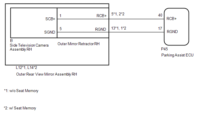
WIRING DIAGRAM
CAUTION / NOTICE / HINT
NOTICE:
-
When "!" mark is displayed on the multi-display assembly after the cable is disconnected from the negative (-) auxiliary battery terminal, correct the steering angle neutral point.
Click here
.gif)
-
Depending on the parts that are replaced or operations that are performed during vehicle inspection or maintenance, calibration of other systems as well as the panoramic view monitor system may be needed.
Click here
PROCEDURE
| 1. | CHECK FOR DTC |
(a) Clear the DTCs.
Click here
(b) Check for DTCs.
Click here
OK:
DTC C1684 is not output.
| Result | Proceed to |
|---|---|
| OK | A |
| NG | B |
| A | .gif) | USE SIMULATION METHOD TO CHECK |
|
.gif)
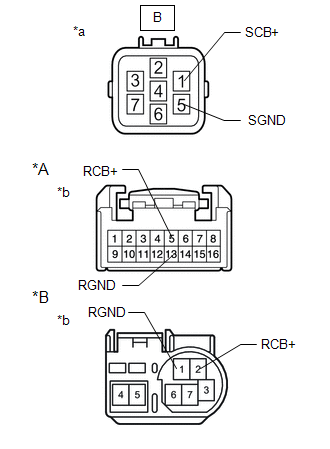
| 2. | CHECK HARNESS AND CONNECTOR (PARKING ASSIST ECU - OUTER REAR VIEW MIRROR ASSEMBLY RH) |
(a) Disconnect the P45 parking assist ECU connector.
(b) Disconnect the L12*1 or L14*2 outer rear view mirror assembly RH connector.
- *1: w/o Seat Memory
- *2: w/ Seat Memory
(c) Measure the resistance according to the value(s) in the table below.
Standard Resistance:
w/o Seat Memory| Tester Connection | Condition | Specified Condition |
|---|---|---|
| P45-40 (RCB+) - L12-5 (RCB+) | Always | Below 1 Ω |
| P45-17 (RGND) - L12-13 (RGND) | Always | Below 1 Ω |
| P45-40 (RCB+) or L12-5 (RCB+) - Body ground | Always | 10 kΩ or higher |
| P45-17 (RGND) or L12-13 (RGND) - Body ground | Always | 10 kΩ or higher |
| Tester Connection | Condition | Specified Condition |
|---|---|---|
| P45-40 (RCB+) - L14-2 (RCB+) | Always | Below 1 Ω |
| P45-17 (RGND) - L14-1 (RGND) | Always | Below 1 Ω |
| P45-40 (RCB+) or L14-2 (RCB+) - Body ground | Always | 10 kΩ or higher |
| P45-17 (RGND) or L14-1 (RGND) - Body ground | Always | 10 kΩ or higher |
| NG | | REPAIR OR REPLACE HARNESS OR CONNECTOR |
|
| 3. | CHECK PARKING ASSIST ECU |
| (a) Disconnect the outer rear view mirror assembly RH connector. |
|
.png)
(b) Measure the resistance according to the value(s) in the table below.
Standard Resistance:
| Tester Connection | Condition | Specified Condition |
|---|---|---|
| P45-17 (RGND) - Body ground | Always | Below 1 Ω |
(c) Measure the voltage according to the value(s) in the table below.
Standard Voltage:
| Tester Connection | Switch Condition | Specified Condition |
|---|---|---|
| P45-40 (RCB+) - P45-17 (RGND) | Power switch on (IG) | 5.5 to 7.05 V |
| P45-40 (RCB+) - P45-17 (RGND) | Power switch off | Below 1 V |
| NG | | REPLACE PARKING ASSIST ECU |
|
| 4. | INSPECT OUTER MIRROR RETRACTOR RH |
| (a) Remove the outer mirror retractor RH. Click here |
|
(b) Measure the resistance according to the value(s) in the table below.
Standard Resistance:
w/o Seat Memory| Tester Connection | Condition | Specified Condition |
|---|---|---|
| B-1 (SCB+) - 5 (RCB+) | Always | Below 1 Ω |
| B-5 (SGND) - 13 (RGND) | Always | Below 1 Ω |
| B-1 (SCB+) or 5 (RCB+) - Body ground | Always | 10 kΩ or higher |
| B-5 (SGND) or 13 (RGND) - Body ground | Always | 10 kΩ or higher |
| Tester Connection | Condition | Specified Condition |
|---|---|---|
| B-1 (SCB+) - 2 (RCB+) | Always | Below 1 Ω |
| B-5 (SGND) - 1 (RGND) | Always | Below 1 Ω |
| B-1 (SCB+) or 2 (RCB+) - Body ground | Always | 10 kΩ or higher |
| B-5 (SGND) or 1 (RGND) - Body ground | Always | 10 kΩ or higher |
| NG | | REPLACE OUTER MIRROR RETRACTOR RH |
|
| 5. | REPLACE SIDE TELEVISION CAMERA ASSEMBLY RH |
(a) Replace the side television camera assembly RH with a new or normally functioning one.
Click here
|
| 6. | CHECK FOR DTC |
(a) Clear the DTCs.
Click here
(b) Check for DTCs.
Click here
OK:
DTC C1684 is not output.
| OK | | END (SIDE TELEVISION CAMERA ASSEMBLY RH IS DEFECTIVE) |
| NG | | REPLACE PARKING ASSIST ECU |
READ NEXT:
 Driver Side Camera Video Sync Signal Malfunction (C1686)
DESCRIPTION This DTC is stored if the parking assist ECU judges as a result of its self check that a synchronization problem is occurring in the image signal sent from the driver side television camer
Over Current Detected in Driver Side Camera (C1687)
DESCRIPTION This DTC is stored if the parking assist ECU judges as a result of its self check that a synchronization problem is occurring in the image signal sent from the driver side television camer
Vehicle Information Unmatched (C168D)
DESCRIPTION This DTC is stored if the parking assist ECU judges as a result of its self check that the vehicle information received via CAN communication and the vehicle information stored in the park
SEE MORE:
Installation
INSTALLATION CAUTION / NOTICE / HINT HINT:
Use the same procedure for the RH and LH sides.
The following procedure is for the LH side.
NOTICE: When the brake pedal is first depressed after replacing the brake pads or pushing back the disc brake piston, DTC C1214 may be output. As there is no
Installation
INSTALLATION PROCEDURE 1. INSTALL NO. 1 COOLER THERMISTOR (a) Install the No. 1 cooler thermistor as shown in the illustration. NOTICE:
Be sure to insert the thermistor only once because reinserting it into the same position will not allow it to be firmly secured.
After inserting the therm
