Lexus NX: Front Damping Force Control Actuator RH Circuit Malfunction (C1731-C1734)
DESCRIPTION
The absorber control actuator changes the damping force depending on absorber control ECU signals.
| DTC No. | Detection Item | DTC Detection Condition | Trouble Area | Warning Indicate |
|---|---|---|---|---|
| C1731 | Front Damping Force Control Actuator RH Circuit Malfunction | Either condition is met:
|
| Does not come on |
| C1732 | Front Damping Force Control Actuator LH Circuit Malfunction | Either condition is met:
|
| Does not come on |
| C1733 | Rear Damping Force Control Actuator RH Circuit Malfunction | Either condition is met:
|
| Does not come on |
| C1734 | Rear Damping Force Control Actuator LH Circuit Malfunction | Either condition is met:
|
| Does not come on |
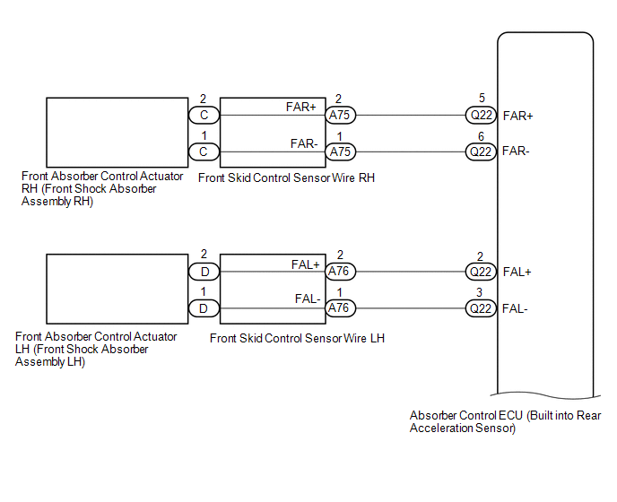
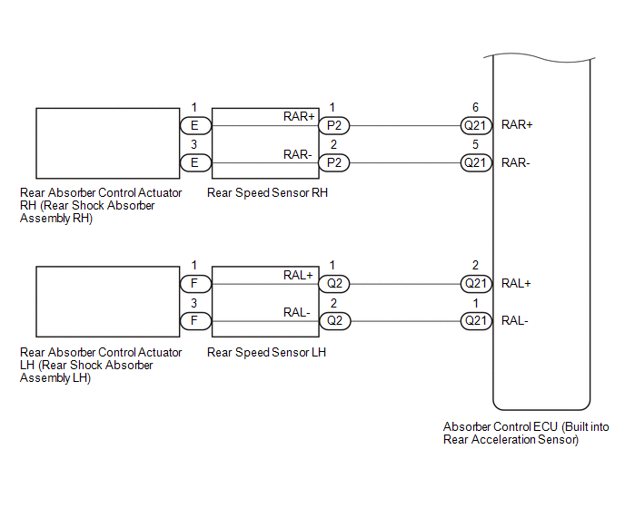
WIRING DIAGRAM
CAUTION / NOTICE / HINT
NOTICE:
- Before performing troubleshooting, inspect the connectors of related circuits.
-
If DTC C1782 (Power Source Voltage Malfunction) is output at the same time, perform troubleshooting for C1782 first.
Click here
.gif)
-
Before replacing the absorber control ECU, perform all of the following again: 1) symptom simulation ; 2) DTC inspection ; and 3) Techstream inspection (ECU Data List or Active Test ). If no malfunctions are found in other areas, replace the absorber control ECU.
-
When the absorber control ECU is replaced, switch to test mode and check that all test mode DTCs are cleared when their respective deletion conditions are met.
Click here
PROCEDURE
| 1. | CLEAR DTC |
(a) Clear the DTCs.
Click here
|
.gif)
| 2. | PERFORM ACTIVE TEST USING TECHSTREAM (DAMPER STEP) |
(a) Turn the power switch off.
(b) Connect the Techstream to the DLC3.
(c) Turn the power switch on (READY).
(d) Turn the Techstream on.
(e) Enter the following menus: Chassis / Air suspension /Active Test.
Chassis > Air suspension > Active Test| Tester Display | Measurement Item | Control Range | Diagnostic Note |
|---|---|---|---|
| Damper Step FR | Changes damper step (front RH) | 1 to 30 step | The shock absorber hardens as the damper step increases. |
| Damper Step FL | Changes damper step (front LH) | 1 to 30 step | The shock absorber hardens as the damper step increases. |
| Damper Step RR | Changes damper step (rear RH) | 1 to 30 step | The shock absorber hardens as the damper step increases. |
| Damper Step RL | Changes damper step (rear LH) | 1 to 30 step | The shock absorber hardens as the damper step increases. |
| Tester Display |
|---|
| Damper Step FR |
| Tester Display |
|---|
| Damper Step FL |
| Tester Display |
|---|
| Damper Step RR |
| Tester Display |
|---|
| Damper Step RL |
(f) When performing the Active Test, read each Tester Display item for the applicable wheel on the Data List and check the operation status of the absorber control actuator for the applicable wheel.
Chassis > Air suspension > Data List| Tester Display | Measurement Item | Range | Normal Condition | Diagnostic Note |
|---|---|---|---|---|
| Damper Step FR | Damper step (front RH) | Min.: 1 step Max.: 255 step | 1 to 30 step | - |
| Damper Step FL | Damper step (front LH) | Min.: 1 step Max.: 255 step | 1 to 30 step | - |
| Damper Step RR | Damper step (rear RH) | Min.: 1 step Max.: 255 step | 1 to 30 step | - |
| Damper Step RL | Damper step (rear LH) | Min.: 1 step Max.: 255 step | 1 to 30 step | - |
| FR Solenoid Aim Electric Current Level for Control | Target solenoid current value (front wheel RH) | Min.: 0 mA Max.: 2040 mA | Changes depending on step count | - |
| FL Solenoid Aim Electric Current Level for Control | Target solenoid current value (front wheel LH) | Min.: 0 mA Max.: 2040 mA | Changes depending on step count | - |
| RR Solenoid Aim Electric Current Level for Control | Target solenoid current value (rear wheel RH) | Min.: 0 mA Max.: 2040 mA | Changes depending on step count | - |
| RL Solenoid Aim Electric Current Level for Control | Target solenoid current value (rear wheel LH) | Min.: 0 mA Max.: 2040 mA | Changes depending on step count | - |
| FR Solenoid Drive Duty | Solenoid drive duty value (front wheel RH) | Min.: 0% Max.: 100% | Changes depending on step count | - |
| FL Solenoid Drive Duty | Solenoid drive duty value (front wheel LH) | Min.: 0% Max.: 100% | Changes depending on step count | - |
| RR Solenoid Drive Duty | Solenoid drive duty value (rear wheel RH) | Min.: 0% Max.: 100% | Changes depending on step count | - |
| RL Solenoid Drive Duty | Solenoid drive duty value (rear wheel LH) | Min.: 0% Max.: 100% | Changes depending on step count | - |
| FR Solenoid Electric Current | Solenoid current value (front wheel RH) | Min.: 0 mA Max.: 2040 mA | Changes depending on step count | - |
| FL Solenoid Electric Current | Solenoid current value (front wheel LH) | Min.: 0 mA Max.: 2040 mA | Changes depending on step count | - |
| RR Solenoid Electric Current | Solenoid current value (rear wheel RH) | Min.: 0 mA Max.: 2040 mA | Changes depending on step count | - |
| RL Solenoid Electric Current | Solenoid current value (rear wheel LH) | Min.: 0 mA Max.: 2040 mA | Changes depending on step count | - |
| Tester Display |
|---|
| Damper Step FR |
| Damper Step FL |
| Damper Step RR |
| Damper Step RL |
| FR Solenoid Aim Electric Current Level for Control |
| FL Solenoid Aim Electric Current Level for Control |
| RR Solenoid Aim Electric Current Level for Control |
| RL Solenoid Aim Electric Current Level for Control |
| FR Solenoid Drive Duty |
| FL Solenoid Drive Duty |
| RR Solenoid Drive Duty |
| RL Solenoid Drive Duty |
| FR Solenoid Electric Current |
| FL Solenoid Electric Current |
| RR Solenoid Electric Current |
| RL Solenoid Electric Current |
OK:
The Data List step numbers, drive duty values and current values change according to the Techstream Active Test operation.
| NG | .gif) | GO TO STEP 4 |
|
| 3. | RECONFIRM DTC |
(a) Check that the same DTC is output.
Click here
| Result | Proceed to |
|---|---|
| DTC is output | A |
| DTC is not output | B |
| B | | USE SIMULATION METHOD TO CHECK |
|
| 4. | INSPECT SHOCK ABSORBER ASSEMBLY |
(a) Turn the power switch off.
(b) Remove the absorber control actuator (shock absorber assembly).
for Front Side: Click here
for Rear Side: Click here
(c) Inspect the absorber control actuator (shock absorber assembly).
for Front Side: Click here
for Rear Side: Click here
| Result | Proceed to |
|---|---|
| OK (for Front Side) | A |
| OK (for Rear Side) | B |
| Front absorber control actuator RH (front shock absorber assembly RH) malfunction | C |
| Front absorber control actuator LH (front shock absorber assembly LH) malfunction | D |
| Rear absorber control actuator RH (rear shock absorber assembly RH) malfunction | E |
| Rear absorber control actuator LH (rear shock absorber assembly LH) malfunction | F |
| B | | GO TO STEP 7 |
| C | | REPLACE FRONT SHOCK ABSORBER ASSEMBLY RH |
| D | | REPLACE FRONT SHOCK ABSORBER ASSEMBLY LH |
| E | | REPLACE REAR SHOCK ABSORBER ASSEMBLY RH |
| F | | REPLACE REAR SHOCK ABSORBER ASSEMBLY LH |
|
| 5. | INSPECT FRONT SKID CONTROL SENSOR WIRE |
(a) Turn the power switch off.
(b) Disconnect the A75 or A76 front skid control sensor wire connector.
(c) Disconnect the C or D front skid control sensor wire connector.
(d) Measure the resistance according to the value(s) in the table below.
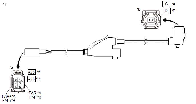
| *A | for RH | *B | for LH |
| *1 | Front Skid Control Sensor Wire | - | - |
| *a | Front view of wire harness connector (to Vehicle Side Connector) | *b | Front view of wire harness connector (to Front Absorber Control Actuator Side Connector) |
Standard Resistance:
for Front RH| Tester Connection | Condition | Specified Condition |
|---|---|---|
| A75-2 (FAR+) - C-2 | Always | Below 1 Ω |
| A75-1 (FAR-) - C-1 | Always | |
| A75-2 (FAR+) or C-2 - Body ground and other terminals | Always | 10 kΩ or higher |
| A75-1 (FAR-) or C-1 - Body ground and other terminals | Always |
| Tester Connection | Condition | Specified Condition |
|---|---|---|
| A76-2 (FAL+) - D-2 | Always | Below 1 Ω |
| A76-1 (FAL-) - D-1 | Always | |
| A76-2 (FAL+) or D-2 - Body ground and other terminals | Always | 10 kΩ or higher |
| A76-1 (FAL-) or D-1- Body ground and other terminals | Always |
| NG | | REPLACE FRONT SKID CONTROL SENSOR WIRE |
|
| 6. | CHECK HARNESS AND CONNECTOR (FRONT SHOCK ABSORBER ASSEMBLY - ABSORBER CONTROL ECU) |
(a) Turn the power switch off.
(b) Disconnect the Q22 absorber control ECU connector.
(c) Connect the A75 or A76 front skid control sensor wire connector.
(d) Measure the resistance according to the value(s) in the table below.
Standard Resistance:
for Front RH| Tester Connection | Condition | Specified Condition |
|---|---|---|
| Q22-5 (FAR+) - C-2 | Always | Below 1 Ω |
| Q22-6 (FAR-) - C-1 | ||
| Q22-5 (FAR+) or C-2 - Body ground | Always | 10 kΩ or higher |
| Q22-6 (FAR-) or C-1 - Body ground |
| Tester Connection | Condition | Specified Condition |
|---|---|---|
| Q22-2 (FAL+) - D-2 | Always | Below 1 Ω |
| Q22-3 (FAL-) - D-1 | ||
| Q22-2 (FAL+) or D-2 - Body ground | Always | 10 kΩ or higher |
| Q22-3 (FAL-) or D-1 - Body ground |
| OK | | REPLACE ABSORBER CONTROL ECU |
| NG | | REPAIR OR REPLACE HARNESS OR CONNECTOR |
| 7. | INSPECT REAR SKID CONTROL SENSOR WIRE OR REAR SPEED SENSOR |
(a) Turn the power switch off.
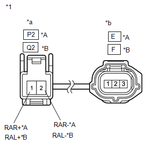
(b) Disconnect the P2 or Q2 rear speed sensor connector.
(c) Disconnect the E or F rear speed sensor connector.
| (d) Measure the resistance according to the value(s) in the table below. Standard Resistance: for Rear RH
|
|
| NG | | REPLACE REAR SPEED SENSOR |
|
| 8. | CHECK HARNESS AND CONNECTOR (REAR SHOCK ABSORBER ASSEMBLY - ABSORBER CONTROL ECU) |
(a) Turn the power switch off.
(b) Disconnect the Q21 absorber control ECU connector.
(c) Connect the P2 or Q2 rear speed sensor connector.
(d) Measure the resistance according to the value(s) in the table below.
Standard Resistance:
for Rear RH| Tester Connection | Condition | Specified Condition |
|---|---|---|
| Q21-6 (RAR+) - E-1 | Always | Below 1 Ω |
| Q21-5 (RAR-) - E-3 | ||
| Q21-6 (RAR+) or E-1 - Body ground | Always | 10 kΩ or higher |
| Q21-5 (RAR-) or E-3 - Body ground |
| Tester Connection | Condition | Specified Condition |
|---|---|---|
| Q21-2 (RAL+) - F-1 | Always | Below 1 Ω |
| Q21-1 (RAL-) - F-3 | ||
| Q21-2 (RAL+) or F-1 - Body ground | Always | 10 kΩ or higher |
| Q21-1 (RAL-) or F-3 - Body ground |
| OK | | REPLACE ABSORBER CONTROL ECU |
| NG | | REPAIR OR REPLACE HARNESS OR CONNECTOR |
READ NEXT:
 Suspension Control ECU Malfunction (C1781)
DESCRIPTION If a malfunction in the absorber control ECU is detected, DTC C1781 is stored. DTC No. Detection Item DTC Detection Condition Trouble Area Warning Indicate C1781 Suspensio
Power Source Voltage Malfunction (C1782)
DESCRIPTION DTC No. Detection Item DTC Detection Condition Trouble Area Warning Indicate C1782 Power Source Voltage Malfunction While the power switch is on (IG), the voltage at ter
Steering Angle Sensor Communication Error (C1784)
DESCRIPTION Steering sensor signals are sent to the absorber control ECU via CAN communication. When there is a communication malfunction, the malfunction will be detected by the diagnosis function.
SEE MORE:
Key-off Operation Function Operates even if Operating Conditions are not Satisfied
DESCRIPTION
When the front doors are closed, each power window regulator motor assembly can control its power window operation for approximately 43 seconds after the power switch is turned from on (IG) to off by receiving operation permission signals from the main body ECU (multiplex network body
Removal
REMOVAL CAUTION / NOTICE / HINT HINT:
Use the same procedure for the RH and LH sides.
The procedure listed below is for the LH side.
PROCEDURE 1. PRECAUTION NOTICE: After turning the power switch off, waiting time may be required before disconnecting the cable from the negative (-) auxiliary
