Lexus NX: Power Source Voltage Malfunction (C1782)
DESCRIPTION
| DTC No. | Detection Item | DTC Detection Condition | Trouble Area | Warning Indicate |
|---|---|---|---|---|
| C1782 | Power Source Voltage Malfunction | While the power switch is on (IG), the voltage at terminal B is 10 V or less, or 16 V or higher for 0.5 seconds. |
| Does not come on |
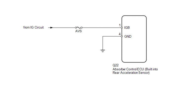
WIRING DIAGRAM
CAUTION / NOTICE / HINT
NOTICE:
- Before performing troubleshooting, inspect the connectors of related circuits.
-
Before replacing the absorber control ECU, perform all of the following again: 1) symptom simulation
.gif) ; 2) DTC inspection ; and 3) Techstream inspection (ECU Data List or Active Test ). If no malfunctions are found in other areas, replace the absorber control ECU.
; 2) DTC inspection ; and 3) Techstream inspection (ECU Data List or Active Test ). If no malfunctions are found in other areas, replace the absorber control ECU.
-
When the absorber control ECU is replaced, switch to test mode and check that all test mode DTCs are cleared when their respective deletion conditions are met.
Click here
- Inspect the fuses for circuits related to this system before performing the following inspection procedure.
PROCEDURE
| 1. | READ VALUE USING TECHSTREAM (IG POWER SOURCE VOLTAGE) |
(a) Turn the power switch off.
(b) Connect the Techstream to the DLC3.
(c) Turn the power switch on (IG).
(d) Turn the Techstream on.
(e) Enter the following menus: Chassis / Air suspension / Data List.
Chassis > Air suspension > Data List| Tester Display | Measurement Item | Range | Normal Condition | Diagnostic Note |
|---|---|---|---|---|
| IG Power Source Voltage | ECU power supply voltage | Min.: 0.0 V Max.: 25.5 V | 11 to 14 V (Actual ECU power supply voltage): Power switch on (IG) | - |
| Tester Display |
|---|
| IG Power Source Voltage |
OK:
The normal condition value is displayed on the Techstream.
| NG | .gif) | GO TO STEP 3 |
|
.gif)
| 2. | CHECK FOR DTC |
(a) Clear the DTCs.
Click here
(b) Turn the power switch off.
(c) Check for DTCs.
Click here
| Result | Proceed to |
|---|---|
| DTC is not output | A |
| DTC is output | B |
| A | | USE SIMULATION METHOD TO CHECK |
| B | | REPLACE ABSORBER CONTROL ECU |
| 3. | INSPECT AUXILIARY BATTERY |
(a) Check the auxiliary battery voltage.
Standard Voltage:
| Tester Connection | Switch Condition | Specified Condition |
|---|---|---|
| Auxiliary battery | Power switch on (IG) | 11 to 14 V |
| Auxiliary battery | Power switch on (READY) | 11 to 15.5 V |
| NG | | CHECK OR REPLACE CHARGING SYSTEM OR BATTERY |
|
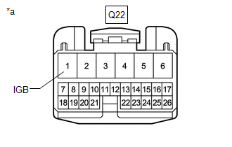
| 4. | CHECK TERMINAL VOLTAGE (IGB) |
(a) Turn the power switch off.
(b) Disconnect the Q22 absorber control ECU connector.
| (c) Measure the voltage according to the value(s) in the table below. Standard Voltage:
|
|
| NG | | REPAIR OR REPLACE HARNESS OR CONNECTOR |
|
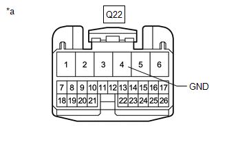
| 5. | CHECK HARNESS AND CONNECTOR (GND TERMINAL) |
(a) Turn the power switch off.
| (b) Measure the resistance according to the value(s) in the table below. Standard Resistance:
|
|
| OK | | REPLACE ABSORBER CONTROL ECU |
| NG | | REPAIR OR REPLACE HARNESS OR CONNECTOR |
READ NEXT:
 Steering Angle Sensor Communication Error (C1784)
DESCRIPTION Steering sensor signals are sent to the absorber control ECU via CAN communication. When there is a communication malfunction, the malfunction will be detected by the diagnosis function.
Vehicle Identification Malfunction (C1789)
DESCRIPTION
When the absorber control ECU has not acquired the vehicle identification information, DTC C1789 is stored. When the vehicle identification information is correctly acquired, this DTC i
Lost Communication With TCM (U0101,U0122,U0124,U0126,U0293)
DESCRIPTION The absorber control ECU receives signals from the skid control ECU (brake booster with master cylinder assembly), steering sensor, airbag ECU assembly (built into acceleration sensor), EC
SEE MORE:
Tilt Position Sensor or Tilt Motor Circuit Malfunction (B2610)
DESCRIPTION The tilt motor is operated by the power source voltage supplied from the multiplex tilt and telescopic ECU and tilts the steering column up and down. The tilt position sensor (Hall IC) in the tilt motor detects the tilt angle of the steering column and sends a signal to the multiplex til
Components
COMPONENTS ILLUSTRATION *1 CLEARANCE LIGHT ASSEMBLY LH *2 CLEARANCE LIGHT ASSEMBLY RH *3 HOOD TO FRONT END PANEL SEAL *4 NO. 3 ENGINE ROOM WIRE *5 RADIATOR GRILLE SUB-ASSEMBLY *6 OUTSIDE MOULDING RETAINER ILLUSTRATION *A w/ Panoramic View Monitor System *B
