Lexus NX: Front Door Courtesy Switch
Components
COMPONENTS
ILLUSTRATION
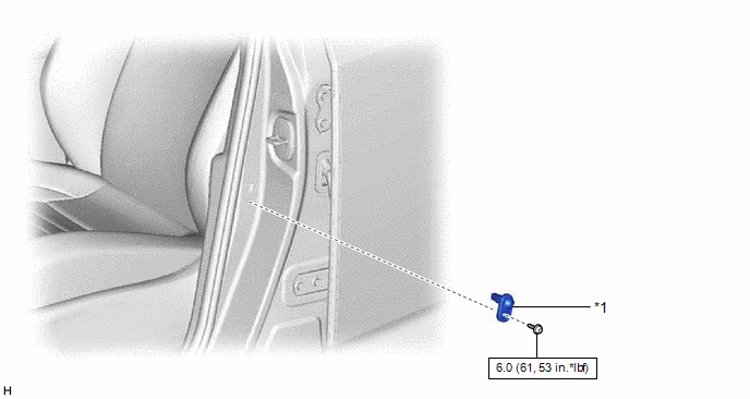
| *1 | FRONT DOOR COURTESY LIGHT SWITCH ASSEMBLY | - | - |
.png) | N*m (kgf*cm, ft.*lbf): Specified torque | - | - |
Removal
REMOVAL
CAUTION / NOTICE / HINT
HINT:
- Use the same procedure for the RH and LH sides.
- The procedure listed below is for the LH side.
PROCEDURE
1. REMOVE FRONT DOOR COURTESY LIGHT SWITCH ASSEMBLY
| (a) Using a T30 "TORX" socket wrench, remove the screw. |
|
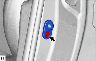
(b) Disconnect the connector and remove the front door courtesy light switch assembly.
Inspection
INSPECTION
CAUTION / NOTICE / HINT
HINT:
- Use the same procedure for the RH and LH sides.
- The procedure listed below is for the LH side.
PROCEDURE
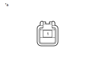
1. INSPECT FRONT DOOR COURTESY LIGHT SWITCH ASSEMBLY
| (a) Measure the resistance according to the value(s) in the table below. Standard Resistance:
If the result is not as specified, replace the front door courtesy light switch assembly. |
|
Installation
INSTALLATION
CAUTION / NOTICE / HINT
HINT:
- Use the same procedure for the RH and LH sides.
- The procedure listed below is for the LH side.
PROCEDURE
1. INSTALL FRONT DOOR COURTESY LIGHT SWITCH ASSEMBLY
(a) Connect the connector.
(b) Using a T30 "TORX" socket wrench, install the front door courtesy light switch assembly with the screw.
Torque:
6.0 N·m {61 kgf·cm, 53 in·lbf}
READ NEXT:
 Components
COMPONENTS ILLUSTRATION *1 DECK FLOOR BOX LH *2 NO. 3 DECK BOARD SUB-ASSEMBLY *3 REAR DECK FLOOR BOX *4 NEGATIVE AUXILIARY BATTERY TERMINAL N*m (kgf*cm, ft.*lbf): Specified
Removal
REMOVAL PROCEDURE 1. DISABLE AUTOAWAY/RETURN FUNCTION (for Power Tilt and Power Telescopic Steering Column) (a) Disable the autoaway/return function by changing the customize parameter. Click here C
SEE MORE:
Freeze Frame Data
FREEZE FRAME DATA FREEZE FRAME DATA (a) Whenever an automatic headlight beam level control system DTC is stored, the headlight ECU subassembly LH stores the current vehicle state as freeze frame data. CHECK FREEZE FRAME DATA (a) Connect the Techstream to the DLC3. (b) Turn the power switch on (IG).
Reassembly
REASSEMBLY CAUTION / NOTICE / HINT HINT:
Use the same procedure for the RH and LH sides.
The procedure listed below is for the LH side.
PROCEDURE 1. INSTALL NO. 2 MOULDING TAPE (a) When using a new rear door rear upper outside moulding LH: (1) Clean the surface of a new rear door rear upper
