Lexus NX: Front Occupant Classification Sensor LH Circuit Malfunction (B1780)
DESCRIPTION
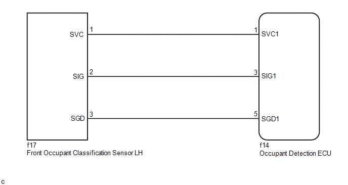
The front occupant classification sensor LH circuit consists of the occupant detection ECU and front occupant classification sensor LH.
DTC B1780 is stored when a malfunction is detected in the front occupant classification sensor LH circuit.
| DTC No. | Detection Item | DTC Detection Condition | Trouble Area |
|---|---|---|---|
| B1780 | Front Occupant Classification Sensor LH Circuit Malfunction | One of the following conditions is met:
|
|
HINT:
- When DTC B1650/32 is stored as a result of troubleshooting the airbag system, perform troubleshooting for DTC B1780 of the occupant classification system.
- Use the Techstream to check for DTCs of the occupant detection ECU, otherwise the DTCs cannot be read.
WIRING DIAGRAM
CAUTION / NOTICE / HINT
NOTICE:
When disconnecting the cable, some systems need to be initialized after the cable is reconnected
Click here .gif)
HINT:
- If troubleshooting (wire harness inspection) is difficult to perform, remove the front seat RH installation bolts to see the undersurface of the seat cushion.
- In the above case, hold the seat so that it does not fall down. Holding the seat for a long period of time may cause problems, such as seat rail deformation. Hold the seat up only for as long as necessary.
PROCEDURE
| 1. | CHECK DTC |
(a) Turn the power switch on (IG), and wait for at least 60 seconds.
(b) Clear the DTCs.
Click here
HINT:
- First clear the DTCs stored in the occupant detection ECU, and then clear the DTCs stored in the airbag ECU assembly.
- Use the Techstream to clear the DTCs of the occupant detection ECU, otherwise the DTCs cannot be cleared.
(c) Turn the power switch off.
(d) Turn the power switch on (IG), and wait for at least 60 seconds.
(e) Check for DTCs.
Click here
HINT:
DTCs other than DTC B1780 may be output at this time, but they are not related to this check.
| DTC B1780 is not output | .gif) | USE SIMULATION METHOD TO CHECK |
|
.gif)
| 2. | CHECK CONNECTION OF CONNECTORS |
(a) Turn the power switch off.
(b) Disconnect the cable from the negative (-) auxiliary battery terminal, and wait for at least 90 seconds.
(c) Check that the connectors are properly connected to the occupant detection ECU and front occupant classification sensor LH.
| Connectors are not properly connected | | CONNECT CONNECTORS |
|
| 3. | CHECK CONNECTORS |
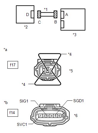
| (a) Disconnect the connectors from the occupant detection ECU and front occupant classification sensor LH. |
|
(b) Check that the connectors (on the occupant detection ECU side and front occupant classification sensor LH side) are not damaged.
Click here
| Connectors are deformed or damaged | | REPLACE FRONT SEAT WIRE RH |
|
| 4. | CHECK FRONT SEAT WIRE RH |
| (a) Connect the cable to the negative (-) auxiliary battery terminal, and wait for at least 2 seconds. |
|
(b) Turn the power switch on (IG).
(c) Measure the voltage according to the value(s) in the table below.
Standard Voltage:
| Tester Connection | Switch Condition | Specified Condition |
|---|---|---|
| f14-1 (SVC1) - Body ground | Power switch on (IG) | Below 1 V |
| f14-3 (SIG1) - Body ground | ||
| f14-5 (SGD1) - Body ground |
(d) Turn the power switch off.
(e) Disconnect the cable from the negative (-) auxiliary battery terminal, and wait for at least 90 seconds.
(f) Using service wires, connect terminals 1 (SVC) and 3 (SGD), and terminals 2 (SIG) and 3 (SGD) of connector C.
NOTICE:
Do not forcibly insert the service wires into the terminals of the connector.
(g) Measure the resistance according to the value(s) in the table below.
Standard Resistance:
| Tester Connection | Condition | Specified Condition |
|---|---|---|
| f14-1 (SVC1) - f14-5 (SGD1) | Always | Below 1 Ω |
| f14-3 (SIG1) - f14-5 (SGD1) |
(h) Disconnect the service wires from connector C.
(i) Measure the resistance according to the value(s) in the table below.
Standard Resistance:
| Tester Connection | Condition | Specified Condition |
|---|---|---|
| f14-1 (SVC1) - f14-5 (SGD1) | Always | 1 MΩ or higher |
| f14-3 (SIG1) - f14-5 (SGD1) | ||
| f14-1 (SVC1) - f14-3 (SIG1) | ||
| f14-1 (SVC1) - Body ground | ||
| f14-3 (SIG1) - Body ground | ||
| f14-5 (SGD1) - Body ground |
| NG | | REPLACE FRONT SEAT WIRE RH |
|
| 5. | CHECK DTC |
(a) Connect the connectors to the occupant detection ECU and front occupant classification sensor LH.
(b) Connect the cable to the negative (-) auxiliary battery terminal, and wait for at least 2 seconds.
(c) Turn the power switch on (IG), and wait for at least 60 seconds.
(d) Clear the DTCs.
Click here
HINT:
- First clear the DTCs stored in the occupant detection ECU, and then clear the DTCs stored in the airbag ECU assembly.
- Use the Techstream to clear the DTCs of the occupant detection ECU, otherwise the DTCs cannot be cleared.
(e) Turn the power switch off.
(f) Turn the power switch on (IG), and wait for at least 60 seconds.
(g) Check for DTCs.
Click here
HINT:
DTCs other than DTC B1780 may be output at this time, but they are not related to this check.
| DTC B1780 is not output | | USE SIMULATION METHOD TO CHECK |
|
| 6. | REPLACE OCCUPANT DETECTION ECU |
(a) Turn the power switch off.
(b) Disconnect the cable from the negative (-) auxiliary battery terminal, and wait for at least 90 seconds.
(c) Replace the occupant detection ECU.
Click here
HINT:
Perform the inspection using parts from a normal vehicle when possible.
|
| 7. | PERFORM ZERO POINT CALIBRATION |
(a) Connect the cable to the negative (-) auxiliary battery terminal, and wait for at least 2 seconds.
(b) Turn the power switch on (IG)
(c) Perform the zero point calibration.
Click here
| "Zero Point Calibration is complete." is not displayed | | GO TO STEP 10 |
|
| 8. | PERFORM SENSITIVITY CHECK |
(a) Perform the sensitivity check.
Click here
Standard:
27 to 33 kg (59.5 to 72.8 lb)
| NG | | GO TO STEP 10 |
|
| 9. | CHECK DTC |
(a) Clear the DTCs.
Click here
HINT:
- First clear the DTCs stored in the occupant detection ECU, and then clear the DTCs stored in the airbag ECU assembly.
- Use the Techstream to clear the DTCs of the occupant detection ECU, otherwise the DTCs cannot be cleared.
(b) Turn the power switch off.
(c) Turn the power switch on (IG), and wait for at least 60 seconds.
(d) Check for DTCs.
Click here
HINT:
DTCs other than DTC B1780 may be output at this time, but they are not related to this check.
| DTC B1780 is not output | | END (OCCUPANT DETECTION ECU WAS DEFECTIVE) |
| DTC B1780 is output | | GO TO STEP 10 |
| 10. | REPLACE FRONT SEAT ADJUSTER ASSEMBLY RH (FRONT OCCUPANT CLASSIFICATION SENSOR LH) |
(a) Turn the power switch off.
(b) Disconnect the cable from the negative (-) auxiliary battery terminal, and wait for at least 90 seconds.
(c) Replace the front seat adjuster assembly RH.
Click here
HINT:
Perform the inspection using parts from a normal vehicle when possible.
|
| 11. | PERFORM ZERO POINT CALIBRATION |
(a) Connect the cable to the negative (-) auxiliary battery terminal, and wait for at least 2 seconds.
(b) Turn the power switch on (IG).
(c) Perform the zero point calibration.
Click here
|
| 12. | PERFORM SENSITIVITY CHECK |
(a) Perform the sensitivity check.
Click here
Standard:
27 to 33 kg (59.5 to 72.8 lb)
| NEXT | | END (FRONT SEAT ADJUSTER ASSEMBLY RH [FRONT OCCUPANT CLASSIFICATION SENSOR LH] WAS DEFECTIVE) |
READ NEXT:
 Rear Occupant Classification Sensor LH Circuit Malfunction (B1782)
DESCRIPTION The rear occupant classification sensor LH circuit consists of the occupant detection ECU and rear occupant classification sensor LH. DTC B1782 is stored when a malfunction is detected in
Front Occupant Classification Sensor LH Collision Detection (B1785)
DESCRIPTION DTC B1785 is stored when the occupant detection ECU receives a collision detection signal, which is sent by the front occupant classification sensor LH when an accident occurs. DTC B1785 i
Rear Occupant Classification Sensor LH Collision Detection (B1787)
DESCRIPTION DTC B1787 is stored when the occupant detection ECU receives a collision detection signal, which is sent by the rear occupant classification sensor LH when an accident occurs. DTC B1787 is
SEE MORE:
Problem Symptoms Table
PROBLEM SYMPTOMS TABLE NOTICE:
When replacing the combination meter assembly, always replace it with a new one. If a combination meter assembly which was installed to another vehicle is used, the information stored in it will not match the information from the vehicle and a DTC may be stored.
I
Removal
REMOVAL CAUTION / NOTICE / HINT HINT:
Use the same procedure for the RH and LH sides.
The procedure listed below is for the LH side.
PROCEDURE 1. REMOVE REAR WIPER ARM HEAD CAP Click here 2. REMOVE REAR WIPER ARM AND BLADE ASSEMBLY Click here 3. REMOVE REAR WIPER MOTOR GROMMET Click here
