Lexus NX: Front Passenger Side Door ECU Communication Stop (B2322)
DESCRIPTION
This DTC is output when LIN communication between the front power window regulator motor assembly RH and main body ECU (multiplex network body ECU) stops for 10 seconds or more.
| DTC No. | Detection Item | DTC Detection Condition | Trouble Area |
|---|---|---|---|
| B2322 | Front Passenger Side Door ECU Communication Stop | No communication between front power window regulator motor assembly RH and main body ECU (multiplex network body ECU) for 10 seconds or more |
|
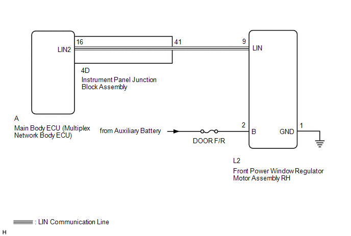
WIRING DIAGRAM
CAUTION / NOTICE / HINT
NOTICE:
-
When using the Techstream with the power switch off to troubleshoot:
Connect the Techstream to the vehicle and turn a courtesy light switch on and off at 1.5 second intervals until communication between the Techstream and vehicle begins.
- Inspect the fuses for circuits related to this system before performing the following procedure.
-
When a power window regulator motor assembly is replaced or removed and reinstalled, it must be initialized.
Click here
.gif)
- Recognition code registration is necessary when replacing the main body ECU (multiplex network body ECU).
-
If the main body ECU (multiplex network body ECU) is replaced, refer to Registration.
Click here
HINT:
DTC B2325 is output when the communication between all of the following components and main body ECU (multiplex network body ECU) stops.
Click here
PROCEDURE
| 1. | CLEAR DTC |
(a) Clear the DTCs.
Click here
|
.gif)
| 2. | CHECK FOR DTC |
(a) Check for DTCs.
Click here
| DTC B2322 is not output | .gif) | USE SIMULATION METHOD TO CHECK |
|
| 3. | CHECK HARNESS AND CONNECTOR (MAIN BODY ECU [MULTIPLEX NETWORK BODY ECU] - FRONT POWER WINDOW REGULATOR MOTOR ASSEMBLY RH) |
(a) Remove the main body ECU (multiplex network body ECU) from the instrument panel junction block assembly.
Click here
(b) Disconnect the L2 front power window regulator motor assembly RH connector.
(c) Measure the resistance according to the value(s) in the table below.
Standard Resistance:
| Tester Connection | Condition | Specified Condition |
|---|---|---|
| A-16 (LIN2) - L2-9 (LIN) | Always | Below 1 Ω |
| A-16 (LIN2) - Body ground | Always | 10 kΩ or higher |
| NG | | GO TO STEP 7 |
|
| 4. | CHECK HARNESS AND CONNECTOR (FRONT POWER WINDOW REGULATOR MOTOR ASSEMBLY RH - BATTERY AND BODY GROUND) |
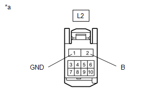
| *a | Front view of wire harness connector (to Front Power Window Regulator Motor Assembly RH) |
(a) Disconnect the front power window regulator motor assembly RH connector.
(b) Measure the resistance according to the value(s) in the table below.
Standard Resistance:
| Tester Connection | Condition | Specified Condition |
|---|---|---|
| L2-1 (GND) - Body ground | Always | Below 1 Ω |
(c) Measure the voltage according to the value(s) in the table below.
Standard Voltage:
| Tester Connection | Switch Condition | Specified Condition |
|---|---|---|
| L2-2 (B) - Body ground | Power switch off | 11 to 14 V |
| NG | | REPAIR OR REPLACE HARNESS OR CONNECTOR |
|
| 5. | REPLACE FRONT POWER WINDOW REGULATOR MOTOR ASSEMBLY RH |
(a) Temporarily replace the front power window regulator motor assembly RH with a new or normally functioning one.
Click here
(b) Clear the DTCs.
Click here
|
| 6. | CHECK FOR DTC |
(a) Check for DTCs.
Click here
| DTC B2322 is not output | | END (FRONT POWER WINDOW REGULATOR MOTOR ASSEMBLY RH IS DEFECTIVE) |
| DTC B2322 is output | | REPLACE MAIN BODY ECU (MULTIPLEX NETWORK BODY ECU) |
| 7. | CHECK HARNESS AND CONNECTOR (INSTRUMENT PANEL JUNCTION BLOCK ASSEMBLY - FRONT POWER WINDOW REGULATOR MOTOR ASSEMBLY RH) |
(a) Remove the main body ECU (multiplex network body ECU) from the instrument panel junction block assembly.
Click here
(b) Disconnect the L2 front power window regulator motor assembly RH connector.
(c) Measure the resistance according to the value(s) in the table below.
Standard Resistance:
| Tester Connection | Condition | Specified Condition |
|---|---|---|
| 4D-41 - L2-9 (LIN) | Always | Below 1 Ω |
| 4D-41 - Body ground | Always | 10 kΩ or higher |
| OK | | REPLACE INSTRUMENT PANEL JUNCTION BLOCK ASSEMBLY |
| NG | | REPAIR OR REPLACE HARNESS OR CONNECTOR |
READ NEXT:
 Rear Door RH ECU Communication Stop (B2323)
DESCRIPTION This DTC is output when LIN communication between the rear power window regulator motor assembly RH and main body ECU (multiplex network body ECU) stops for 10 seconds or more. DTC No.
Rear Door LH ECU Communication Stop (B2324)
DESCRIPTION This DTC is output when LIN communication between the rear power window regulator motor assembly LH and main body ECU (multiplex network body ECU) stops for 10 seconds or more. DTC No.
LIN Communication Bus Malfunction (B2325)
DESCRIPTION
*1: w/ Sliding Roof System
*2: w/ Hands Free Power Back Door
The main body ECU (multiplex network body ECU) intermittently monitors the LIN communication bus between the components
SEE MORE:
Short to GND or Open in Buzzer (C1ABE)
DESCRIPTION This DTC is stored when the blind spot monitor sensor RH detects a ground short or open in the RCTA buzzer (blind spot monitor buzzer) circuit. DTC No. Detection Item DTC Detection Condition Trouble Area Note C1ABE Short to GND or Open in Buzzer Both of the following
Precaution
PRECAUTION POWER FOLDING SEAT FUNCTION HANDLING PRECAUTIONS NOTICE:
When operating the rear power seat, make sure nothing is in the path of movement.
When operating the rear power seat, do not allow body parts or foreign objects to interfere with the seat or other components as injuries or dama
