Lexus NX: LIN Communication Bus Malfunction (B2325)
DESCRIPTION
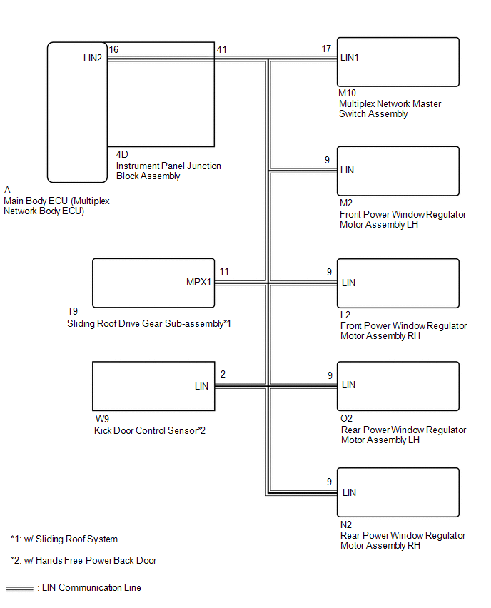
- *1: w/ Sliding Roof System
- *2: w/ Hands Free Power Back Door
The main body ECU (multiplex network body ECU) intermittently monitors the LIN communication bus between the components related to the doors, sliding roof drive gear sub-assembly*1 and kick door control sensor*2. DTC B2325 is stored when a malfunction in the LIN communication bus between the components related to the doors and sliding roof drive gear sub-assembly is detected consecutively 3 times.
| DTC No. | Detection Item | DTC Detection Condition | Trouble Area |
|---|---|---|---|
| B2325 | LIN Communication Bus Malfunction | Main body ECU (multiplex network body ECU) detects errors in communication with the ECUs connected to the door bus lines 3 times in a row. |
|
WIRING DIAGRAM
CAUTION / NOTICE / HINT
NOTICE:
-
When using the Techstream with the power switch off to troubleshoot:
Connect the Techstream to the vehicle and turn a courtesy light switch on and off at 1.5 second intervals until communication between the Techstream and vehicle begins.
-
When the power window regulator motor assembly (driver side) is removed and reinstalled or replaced, the power window regulator motor assembly (driver side) must be initialized.
Click here
.gif)
-
w/ Sliding Roof System:
When the sliding roof drive gear sub-assembly is removed and reinstalled or replaced, the sliding roof drive gear sub-assembly must be initialized.
Click here
- Recognition code registration is necessary when replacing the main body ECU (multiplex network body ECU).
-
If the main body ECU (multiplex network body ECU) is replaced, refer to Registration.
Click here
HINT:
When DTC B2325 and a LIN communication stop DTC are output simultaneously, first perform troubleshooting for DTC B2325. Then perform troubleshooting for the LIN communication stop DTC.
PROCEDURE
| 1. | CLEAR DTC |
(a) Clear the DTCs.
Click here
|
.gif)
| 2. | CHECK FOR DTC |
(a) Check for DTCs.
Click here
| DTC B2325 is not output | .gif) | USE SIMULATION METHOD TO CHECK |
|
| 3. | CHECK MULTIPLEX NETWORK MASTER SWITCH ASSEMBLY |
(a) Clear the DTCs.
Click here
(b) Disconnect the M10 multiplex network master switch assembly connector.
(c) Check for DTCs.
Click here
| DTC B1206 is output | | REPLACE MULTIPLEX NETWORK MASTER SWITCH ASSEMBLY |
|
| 4. | CHECK FRONT POWER WINDOW REGULATOR MOTOR ASSEMBLY LH |
(a) Clear the DTCs.
Click here
(b) Disconnect the M2 front power window regulator motor assembly LH connector.
(c) Check for DTCs.
Click here
| DTC B2321 is output | | REPLACE FRONT POWER WINDOW REGULATOR MOTOR ASSEMBLY LH |
|
| 5. | CHECK FRONT POWER WINDOW REGULATOR MOTOR ASSEMBLY RH |
(a) Clear the DTCs.
Click here
(b) Disconnect the L2 front power window regulator motor assembly RH connector.
(c) Check for DTCs.
Click here
| DTC B2322 is output | | REPLACE POWER WINDOW REGULATOR MOTOR ASSEMBLY RH |
|
| 6. | CHECK REAR POWER WINDOW REGULATOR MOTOR ASSEMBLY LH |
(a) Clear the DTCs.
Click here
(b) Disconnect the O2 rear power window regulator motor assembly LH connector.
(c) Check for DTCs.
Click here
| DTC B2323 is output | | REPLACE POWER WINDOW REGULATOR MOTOR ASSEMBLY LH |
|
| 7. | CHECK REAR POWER WINDOW REGULATOR MOTOR ASSEMBLY RH |
(a) Clear the DTCs.
Click here
(b) Disconnect the N2 rear power window regulator motor assembly RH connector.
(c) Check for DTCs.
Click here
| DTC B2324 is output | | REPLACE REAR POWER WINDOW REGULATOR MOTOR ASSEMBLY RH |
|
| 8. | CHECK SLIDING ROOF DRIVE GEAR SUB-ASSEMBLY |
NOTICE:
For vehicle without a sliding loof system, proceed to next step.
(a) Clear the DTCs.
Click here
(b) Disconnect the T9 sliding roof drive gear sub-assembly connector.
(c) Check for DTCs.
Click here
| DTC B1273 is output | | REPLACE SLIDING ROOF DRIVE GEAR SUB-ASSEMBLY |
|
| 9. | CHECK KICK DOOR CONTROL SENSOR |
NOTICE:
For vehicle without a hands free power back door, proceed to next step.
(a) Clear the DTCs.
Click here
(b) Disconnect the W9 kick door control sensor connector.
(c) Check for DTCs.
Click here
| DTC B2325 is output | | REPLACE KICK DOOR CONTROL SENSOR |
|
| 10. | CHECK HARNESS AND CONNECTOR (MAIN BODY ECU [MULTIPLEX NETWORK BODY ECU] - MULTIPLEX NETWORK MASTER SWITCH ASSEMBLY) |
(a) Disconnect the 4D instrument panel junction block assembly connector.
(b) Disconnect the M10 multiplex network master switch assembly connector.
(c) Disconnect the M2 front power window regulator motor assembly LH connector.
(d) Disconnect the L2 front power window regulator motor assembly RH connector.
(e) Disconnect the O2 rear power window regulator motor assembly LH connector.
(f) Disconnect the N2 rear power window regulator motor assembly RH connector.
(g) w/ Sliding Roof System:
(1) Disconnect the T9 sliding roof drive gear sub-assembly connector.
(h) w/ Hands Free Power Door:
(1) Disconnect the W9 kick door control sensor connector.
(i) Measure the resistance according to the value(s) in the table below.
Standard Resistance:
| Tester Connection | Condition | Specified Condition |
|---|---|---|
| M10-17 (LIN1) - Body ground | Always | 10 kΩ or higher |
| NG | | REPAIR OR REPLACE HARNESS OR CONNECTOR |
|
| 11. | CHECK HARNESS AND CONNECTOR (MAIN BODY ECU [MULTIPLEX NETWORK BODY ECU] - BODY GROUND) |
(a) Remove the main body ECU (multiplex network body ECU) from the instrument panel junction block assembly.
Click here
(b) Connect the instrument panel junction block assembly connectors.
(c) Measure the resistance according to the value(s) in the table below.
Standard Resistance:
| Tester Connection | Condition | Specified Condition |
|---|---|---|
| A-16 (LIN2) - Body ground | Always | 10 kΩ or higher |
| OK | | REPLACE MAIN BODY ECU (MULTIPLEX NETWORK BODY ECU) |
| NG | | REPLACE INSTRUMENT PANEL JUNCTION BLOCK ASSEMBLY |
READ NEXT:
 Communication Malfunction between ECUs Connected by LIN (B2785)
DESCRIPTION The certification ECU intermittently monitors the LIN communication bus between the components related to certification. DTC B2785 is stored when a malfunction in the LIN communication bus
No Response from Steering Lock ECU (B2786)
DESCRIPTION This DTC is stored when LIN communication between the certification ECU (smart key ECU assembly) and steering lock actuator stops for 10 seconds or more. DTC No. Detection Item DTC
No Response from ID BOX (B2789)
DESCRIPTION This DTC is stored when LIN communication between the certification ECU (smart key ECU assembly) and ID code box (immobiliser code ECU) stops for 10 seconds or more. DTC No. Detection
SEE MORE:
Extension Module Malfunction 2 (B1556)
DESCRIPTION These DTCs are stored when a malfunction occurs in the Navigation ECU. DTC No. Detection Item DTC Detection Condition Trouble Area B1556 Extension Module Malfunction 2 When any of the following conditions is met:
Internal hard drive malfunction
EEPROM error
Storag
ECM Communication Stop Mode
DESCRIPTION Detection Item Symptom Trouble Area ECM Communication Stop Mode Any of the following conditions are met:
Communication stop for "Engine" is indicated on the "Communication Bus Check" screen of the Techstream.
Click here
Communication system DTCs (DTCs that start wit
