Lexus NX: Operation Check
OPERATION CHECK
ICS OFF INDICATOR LIGHT OPERATION CHECK
(a) Turn the power switch on (IG).
(b) Turn the intelligent clearance sonar system off and confirm that the ICS OFF indicator in the combination meter illuminates.
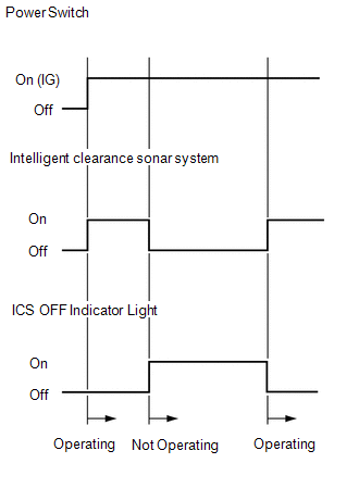
HINT:
If the intelligent clearance sonar system is not set to off in the customize settings, the intelligent clearance sonar system will operate when the power switch is turned on (IG).
DETECTION AREA
(a) Intelligent clearance sonar system detection distance
-
The ultrasonic sensors (front/rear center sensor) can detect objects up to a distance of approximately 4.0 m (13.124 ft.). However, the detection distance varies depending on the shape of the object.
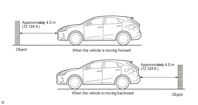
HINT:
The detection range shown in the illustration is for when detecting an object that is 2.0 m (6.562 ft.) wide, 1.0 m (3.281 ft.) tall and is perpendicular to the ground.
- If the front/rear sensors and left/right sensors do not simultaneously detect an object, the intelligent clearance sonar function does not operate.
NOTICE:
Even if the intelligent clearance sonar system detects an object, the system may not operate depending on the vehicle conditions.
READ NEXT:
 Customize Parameters
CUSTOMIZE PARAMETERS CUSTOMIZE INTELLIGENT CLEARANCE SONAR SYSTEM (a) Customizing with the Techstream. NOTICE:
When the customer requests a change in a function, first make sure that the function c
Calibration
CALIBRATION NOTICE: When any of the following parts have been replaced, perform adjustment shown in the following table. If not, the intelligent clearance sonar system may not operate correctly. PRECA
Utility
UTILITY FREEZE FRAME DATA NOTICE:
Freeze frame data is stored and updated each time the brakes are operated. Only the latest 30 sets of data are stored.
Using the Techstream, make sure to save th
SEE MORE:
Visual Mute Signal Circuit between Radio Receiver and Multi-display
DESCRIPTION The radio receiver assembly sends a visual mute signal to the multi-display assembly. As a result, a black screen is inserted when the screen changes so that noise and distorted images are not displayed. When an open exists in the circuit, noise and distorted images will be displayed ins
Removal
REMOVAL CAUTION / NOTICE / HINT PROCEDURE 1. REMOVE ELECTRIC POWER STEERING COLUMN SUB-ASSEMBLY Click here 2. REMOVE POWER STEERING ECU ASSEMBLY (a) Detach the claw and remove the power steering ECU protector from the power steering ECU assembly. (b) Remove the 2 cable ties and h
