- DTC judgment completed
- System normal
Lexus NX: Fuel Level Sensor "A" Circuit Low (P0462,P0463)
Lexus NX Service Manual / Engine & Hybrid System / 2ar-fxe (engine Control) / Sfi System / Fuel Level Sensor "A" Circuit Low (P0462,P0463)
DESCRIPTION
Refer to DTC P0461.
Click here .gif)
| DTC No. | Detection Item | DTC Detection Condition | Trouble Area | MIL | Memory |
|---|---|---|---|---|---|
| P0462 | Fuel Level Sensor "A" Circuit Low | Fuel sender gauge output resistance is less than 7 Ω for 30 seconds or more (1 trip detection logic). |
| Comes on | DTC stored |
| P0463 | Fuel Level Sensor "A" Circuit High | Fuel sender gauge output resistance is higher than 480 Ω for 30 seconds or more (2 trip detection logic). |
| Comes on | DTC stored |
MONITOR DESCRIPTION
When the power switch is turned on (IG) and the fuel sender gauge resistance value sent from the combination meter assembly via CAN communication indicates the resistance is less than 7Ω or exceeds 480Ω continuously for 30 seconds, the ECM illuminates the MIL and a DTC is stored.
MONITOR STRATEGY
| Related DTCs | P0462: Fuel level sensor range check (Low Resistance) P0463: Fuel level sensor range check (High Resistance) |
| Required Sensors/Components (Main) | Fuel sender gauge |
| Required Sensors/Components (Related) | - |
| Frequency of Operation | Continuous |
| Duration | 30 seconds |
| MIL Operation | P0462: 1 driving cycles P0463: 2 driving cycles |
| Sequence of Operation | None |
TYPICAL ENABLING CONDITIONS
| Auxiliary battery voltage | 8 V or higher |
| Power switch | On (IG) |
| Time after power switch turned from off to on (IG) | 0.5 seconds or more |
| Vehicle speed | 40 km/h (24.86 mph) or higher for 30 seconds or more |
| Vehicle speed sensor circuit failure (P0500) | Not detected |
| Lost communication with IPC control module (U0155) | Not detected |
TYPICAL MALFUNCTION THRESHOLDS
P0462| Fuel sender gauge resistance | Less than 7 Ω |
| Fuel sender gauge resistance | Higher than 480 Ω |
CONFIRMATION DRIVING PATTERN
- Connect the Techstream to the DLC3.
- Turn the power switch on (IG).
- Turn the Techstream on.
- Clear the DTCs (even if no DTCs are stored, perform the clear DTC procedure).
- Turn the power switch off and wait for at least 30 seconds.
- Turn the power switch on (IG).
- Turn the Techstream on.
- Wait 30 seconds or more.
- Enter the following menus: Powertrain / Engine and ECT / Trouble Codes.
-
Read the pending DTCs.
HINT:
- If a pending DTC is output, the system is malfunctioning.
- If a pending DTC is not output, perform the following procedure.
- Enter the following menus: Powertrain / Engine and ECT / Utility / All Readiness.
- Input the DTC: P0462 or P0463.
-
Check the DTC judgment result.
Techstream Display
Description
NORMAL
ABNORMAL
- DTC judgment completed
- System abnormal
INCOMPLETE
- DTC judgment not completed
- Perform driving pattern after confirming DTC enabling conditions
N/A
- Unable to perform DTC judgment
- Number of DTCs which do not fulfill DTC preconditions has reached ECU memory limit
HINT:
- If the judgment result shows NORMAL, the system is normal.
- If the judgment result shows ABNORMAL, the system has a malfunction.
-
If the judgment result is INCOMPLETE or N/A and no pending DTC is output, perform a universal trip and check for permanent DTCs.
Click here
HINT:
- If a permanent DTC is output, the system is malfunctioning.
- If no permanent DTC is output, the system is normal.
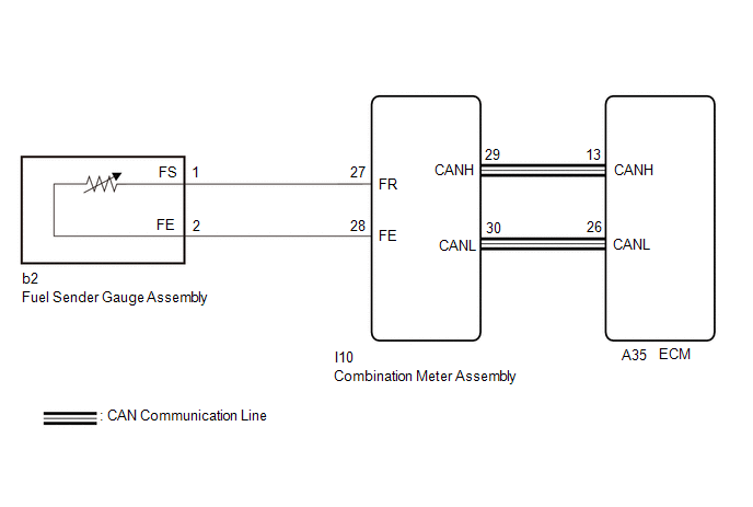
WIRING DIAGRAM
CAUTION / NOTICE / HINT
HINT:
Read freeze frame data using the Techstream. The ECM records vehicle and driving condition information as freeze frame data the moment a DTC is stored. When troubleshooting, freeze frame data can help determine if the vehicle was moving or stationary, if the engine was warmed up or not, if the air fuel ratio was lean or rich, and other data from the time the malfunction occurred.
PROCEDURE
| 1. | CHECK HARNESS AND CONNECTOR (FUEL SENDER GAUGE ASSEMBLY - COMBINATION METER ASSEMBLY) |
(a) Disconnect the fuel sender gauge assembly connector.
(b) Disconnect the combination meter assembly connector.
(c) Measure the resistance according to the value(s) in the table below.
Standard Resistance:
| Tester Connection | Condition | Specified Condition |
|---|---|---|
| I10-27 (FR) - b2-1 (FS) | Always | Below 1 Ω |
| I10-28 (FE) - b2-2 (FE) | Always | Below 1 Ω |
| I10-27 (FR) or b2-1 (FS) - Body ground and other terminals | Always | 10 kΩ or higher |
| I10-28 (FE) or b2-2 (FE) - Body ground and other terminals | Always | 10 kΩ or higher |
| NG | .gif) | REPAIR OR REPLACE HARNESS OR CONNECTOR |
|
.gif)
| 2. | INSPECT FUEL SENDER GAGE ASSEMBLY |
(a) Remove the fuel sender gauge assembly.
Click here
(b) Inspect the fuel sender gauge assembly.
Click here
| OK | | REPLACE COMBINATION METER ASSEMBLY |
| NG | | REPLACE FUEL SENDER GAGE ASSEMBLY |
READ NEXT:
 Idle Control System (P0505)
DESCRIPTION The idle speed is controlled by the electronic throttle control system. The electronic throttle control system is comprised of: 1) one valve type throttle body with motor assembly; 2) the
Cold Start Idle Air Control System Performance (P050A)
MONITOR DESCRIPTION This monitor will run when the engine is started at an engine coolant temperature of -10 to 50°C (14 to 122°F). The DTC will be stored after the engine idles for 13 seconds (2 tr
Cold Start Ignition Timing Performance (P050B)
MONITOR DESCRIPTION This monitor will run when the engine is started at an engine coolant temperature of -10 to 50°C (14 to 122°F). The DTC is stored after the engine idles for 13 seconds (2 trip de
SEE MORE:
Removal
REMOVAL PROCEDURE 1. TABLE OF BOLT, SCREW AND CLIP HINT: All bolts, screws, and clips relevant to installing and removing the instrument panel are shown along with their alphabet code in the table below. 2. DISABLE AUTOAWAY/RETURN FUNCTION (for Power Tilt and Power Telescopic Steering Column) (a) D
Components
COMPONENTS ILLUSTRATION *1 CONSOLE ARMREST ASSEMBLY *2 INSTRUMENT SIDE PANEL LH *3 LOWER NO. 1 INSTRUMENT PANEL FINISH PANEL *4 NO. 1 INSTRUMENT PANEL SAFETY PAD SUB-ASSEMBLY *5 NO. 1 INSTRUMENT PANEL UNDER COVER SUB-ASSEMBLY *6 NO. 1 SWITCH HOLE BASE *7 UPPER NO.
© 2016-2026 Copyright www.lexunx.com
