- DTC judgment completed
- System normal
Lexus NX: Fuel Level Sensor "A" Circuit Range / Performance (P0461)
Lexus NX Service Manual / Engine & Hybrid System / 2ar-fxe (engine Control) / Sfi System / Fuel Level Sensor "A" Circuit Range / Performance (P0461)
DESCRIPTION
The fuel sender gauge is located inside the fuel tank and measures the amount of fuel. The fuel sender gauge converts the fuel level in the fuel tank into a output value, and outputs this value. The ECM determines when it is necessary to refuel the vehicle based on changes in the output value of the fuel sender gauge.
| DTC No. | Detection Item | DTC Detection Condition | Trouble Area | MIL | Memory |
|---|---|---|---|---|---|
| P0461 | Fuel Level Sensor "A" Circuit Range / Performance | Despite consuming a certain amount of fuel, the change in the output value of the fuel sender gauge is below the threshold. (1 trip detection logic). |
| Comes on | DTC stored |
MONITOR DESCRIPTION
When the fuel sender gauge assembly output value changes less than a specified amount, when compared to the fuel consumption calculated from the fuel injection volume, the ECM will detect a malfunction, illuminate the MIL and store a DTC.
MONITOR STRATEGY
| Related DTCs | P0461: Fuel level sensor stuck |
| Required Sensors/Components (Main) | Fuel sender gauge |
| Required Sensors/Components (Related) | - |
| Frequency of Operation | Continuous |
| Duration | Less than 10 seconds |
| MIL Operation | 1 driving cycles |
| Sequence of Operation | None |
TYPICAL ENABLING CONDITIONS
| Lost communication with instrument panel cluster control module (U0155) | Not detected |
| Fuel level sensor circuit malfunction (P0462, P0463) | Not detected |
| Either of the following conditions is met | Condition A or B |
| A. Auxiliary battery voltage | 8.0 V or higher |
| B. Check mode | On |
| Fuel level sensor output via CAN | Received |
| Power switch | On (IG) |
TYPICAL MALFUNCTION THRESHOLDS
| One of the following conditions is met | A, B or C |
| A. Accumulated volume of injected fuel during (a) is met at high fuel level | 19.7 L or more |
| B. Accumulated volume of injected fuel during (a) is met at middle fuel level | 5.6 L or more |
| C. Accumulated volume of injected fuel during (a) is met at low fuel level | 32.1 L or more |
| (a) Smoothed fuel level sensor output (Maximum - Minimum) | Less than 2.8 L |
CONFIRMATION DRIVING PATTERN
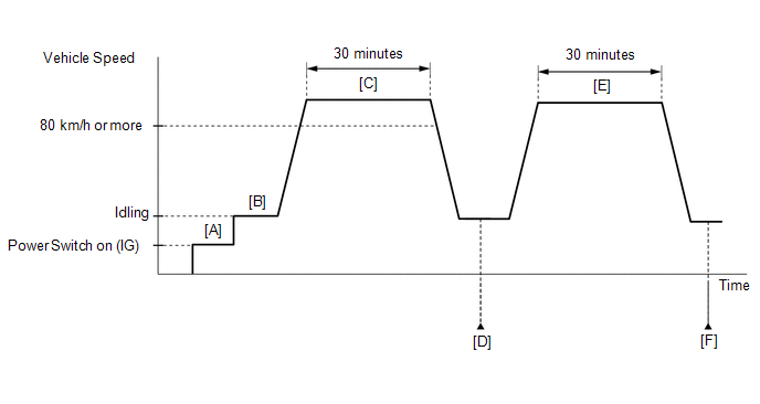
- Connect the Techstream to the DLC3.
- Turn the power switch on (IG).
- Turn the Techstream on.
- Clear the DTCs (even if no DTCs are stored, perform the clear DTC procedure).
- Turn the power switch off and wait for at least 30 seconds.
- Turn the power switch on (IG) [A].
- Turn the Techstream on.
- Start the engine [B].
- Drive the vehicle at 80 km/h (50 mph) or more for 30 minutes [C].
- Enter the following menus: Powertrain / Engine and ECT / Trouble Codes [D].
-
Read the pending DTCs.
HINT:
- If a pending DTC is output, the system is malfunctioning.
- If a pending DTC is not output, perform the following procedure.
- Enter the following menus: Powertrain / Engine and ECT / Utility / All Readiness.
- Input the DTC: P0461.
-
Check the DTC judgment result.
Techstream Display
Description
NORMAL
ABNORMAL
- DTC judgment completed
- System abnormal
INCOMPLETE
- DTC judgment not completed
- Perform driving pattern after confirming DTC enabling conditions
N/A
- Unable to perform DTC judgment
- Number of DTCs which do not fulfill DTC preconditions has reached ECU memory limit
HINT:
- If the judgment result shows NORMAL, the system is normal.
- If the judgment result shows ABNORMAL, the system has a malfunction.
- If the judgment result is INCOMPLETE or N/A, perform steps [E] through [F].
- Drive the vehicle at 80 km/h (50 mph) or more for 30 minutes [E].
- Enter the following menus: Powertrain / Engine and ECT / Trouble Codes [F].
-
Read the pending DTCs.
HINT:
- If a pending DTC is output, the system is malfunctioning.
- If a pending DTC is not output, perform the following procedure.
- Enter the following menus: Powertrain / Engine and ECT / Utility / All Readiness.
- Input the DTC: P0461.
-
Check the DTC judgment result.
Techstream Display
Description
NORMAL
- DTC judgment completed
- System normal
ABNORMAL
- DTC judgment completed
- System abnormal
INCOMPLETE
- DTC judgment not completed
- Perform driving pattern after confirming DTC enabling conditions
N/A
- Unable to perform DTC judgment
- Number of DTCs which do not fulfill DTC preconditions has reached ECU memory limit
HINT:
- If the judgment result shows NORMAL, the system is normal.
- If the judgment result shows ABNORMAL, the system has a malfunction.
-
If the judgment result is INCOMPLETE or N/A and no pending DTC is output, perform a universal trip and check for permanent DTCs.
Click here
.gif)
HINT:
- If a permanent DTC is output, the system is malfunctioning.
- If no permanent DTC is output, the system is normal.
CAUTION / NOTICE / HINT
HINT:
Read freeze frame data using the Techstream. The ECM records vehicle and driving condition information as freeze frame data the moment a DTC is stored. When troubleshooting, freeze frame data can help determine if the vehicle was moving or stationary, if the engine was warmed up or not, if the air fuel ratio was lean or rich, and other data from the time the malfunction occurred.
PROCEDURE
| 1. | INTERVIEW THE CUSTOMER |
(a) Interview the customer for details about when the they refuel the vehicle.
HINT:
When the fuel tank is full, if the vehicle is repeatedly driven a short distance and then refueled, the fuel sender gauge output value will not change. In this case, the ECM may judge that the fuel sender gauge is stuck and store DTC P0461. If the vehicle was driven in this manner, as the DTC was stored due to a user action, clear the DTCs without performing troubleshooting and return the vehicle to the customer.
|
.gif)
| 2. | INSPECT FUEL SENDER GAUGE ASSEMBLY |
(a) Remove the fuel sender gauge assembly.
Click here
(b) Inspect the fuel sender gauge assembly.
Click here
| OK | .gif) | CHECK FOR INTERMITTENT PROBLEMS |
| NG | | REPLACE FUEL SENDER GAUGE ASSEMBLY |
READ NEXT:
 Fuel Level Sensor "A" Circuit Low (P0462,P0463)
DESCRIPTION Refer to DTC P0461. Click here DTC No. Detection Item DTC Detection Condition Trouble Area MIL Memory P0462 Fuel Level Sensor "A" Circuit Low Fuel sender gauge outp
Idle Control System (P0505)
DESCRIPTION The idle speed is controlled by the electronic throttle control system. The electronic throttle control system is comprised of: 1) one valve type throttle body with motor assembly; 2) the
Cold Start Idle Air Control System Performance (P050A)
MONITOR DESCRIPTION This monitor will run when the engine is started at an engine coolant temperature of -10 to 50°C (14 to 122°F). The DTC will be stored after the engine idles for 13 seconds (2 tr
SEE MORE:
Installation
INSTALLATION CAUTION / NOTICE / HINT HINT:
Use the same procedure for the RH and LH sides.
The procedure listed below is for the LH side.
PROCEDURE 1. INSTALL SIDE AIRBAG SENSOR ASSEMBLY LH (a) Check that the power switch is off. (b) Check that the cable is disconnected from the negative (-)
Removal
REMOVAL PROCEDURE 1. REMOVE FUEL TANK ASSEMBLY Click here 2. DISCONNECT FUEL TANK MAIN TUBE SUB-ASSEMBLY (a) Remove the tube joint clip, then disconnect the fuel tank main tube sub-assembly from the fuel suction plate sub-assembly. NOTICE:
Remove dirt or foreign objects on the fuel tube j
© 2016-2026 Copyright www.lexunx.com
