Lexus NX: Removal
REMOVAL
PROCEDURE
1. REMOVE FUEL TANK ASSEMBLY
Click here .gif)
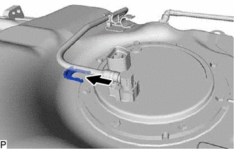
2. DISCONNECT FUEL TANK MAIN TUBE SUB-ASSEMBLY
| (a) Remove the tube joint clip, then disconnect the fuel tank main tube sub-assembly from the fuel suction plate sub-assembly. NOTICE:
|
|
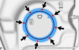
3. REMOVE FUEL TANK VENT TUBE SET PLATE
| (a) Remove the 8 bolts and fuel tank vent tube set plate. |
|
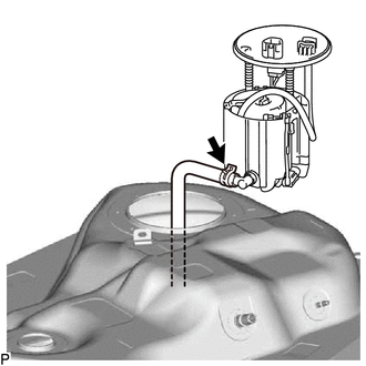
4. REMOVE FUEL SUCTION TUBE ASSEMBLY
| (a) Slide the clamp, disconnect the fuel hose from the fuel suction tube assembly, then remove the fuel suction tube assembly from the fuel tank assembly. NOTICE: Be careful not to damage the fuel suction tube assembly. |
|
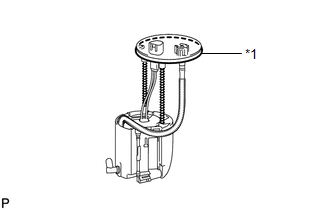
| (b) Remove the gasket from the fuel suction tube assembly. |
|
READ NEXT:
 Disassembly
DISASSEMBLY CAUTION / NOTICE / HINT NOTICE: Do not try to remove the black nylon tube as it is welded to the fuel suction tube assembly. Click here PROCEDURE 1. REMOVE NO. 1 FUEL SUB-TANK (a) Di
Inspection
INSPECTION PROCEDURE 1. INSPECT FUEL PUMP ASSEMBLY WITH FILTER (a) Check the resistance. (1) Measure the resistance according to the value(s) in the table below. Standard Resistance: Tester Con
Reassembly
REASSEMBLY CAUTION / NOTICE / HINT NOTICE: Do not try to remove the black nylon tube as it is welded to the fuel suction tube assembly. Click here HINT: Perform "Inspection After Repairs" after rep
SEE MORE:
Camera Heater
ComponentsCOMPONENTS ILLUSTRATION *1 FORWARD RECOGNITION WITH HEATER HOOD SUB-ASSEMBLY - - RemovalREMOVAL PROCEDURE 1. REMOVE FORWARD RECOGNITION CAMERA Click here 2. REMOVE FORWARD RECOGNITION WITH HEATER HOOD SUB-ASSEMBLY NOTICE:
Do not touch the inner surface of the forward re
Rear Power Seat Switch Circuit
DESCRIPTION When the rear power seat switch is operated, a recline signal is sent to the fold seat control ECU. The ECU activates the power seat motor based on the signal from the rear power seat switch. WIRING DIAGRAM PROCEDURE 1. INSPECT REAR POWER SEAT SWITCH (a) Remove the rear power s
© 2016-2026 Copyright www.lexunx.com
