Lexus NX: Heated Oxygen Sensor
Components
COMPONENTS
ILLUSTRATION
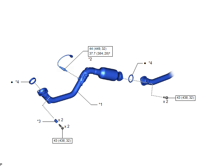
| *1 | FRONT EXHAUST PIPE SUB-ASSEMBLY | *2 | HEATED OXYGEN SENSOR |
| *3 | COMPRESSION SPRING | *4 | GASKET |
.png) | N*m (kgf*cm, ft.*lbf): Specified torque | * | For use with SST |
| ● | Non-reusable part | - | - |
Removal
REMOVAL
PROCEDURE
1. REMOVE FRONT EXHAUST PIPE SUB-ASSEMBLY
Click here .gif)
2. REMOVE HEATED OXYGEN SENSOR
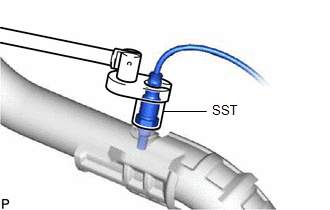
| (a) Using SST, remove the heated oxygen sensor. SST: 09224-00011 |
|
Inspection
INSPECTION
PROCEDURE
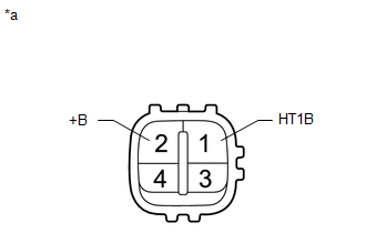
1. INSPECT HEATED OXYGEN SENSOR
| (a) Measure the resistance according to the value(s) in the table below. Standard Resistance:
If the result is not as specified, replace the heated oxygen sensor. |
|
Installation
INSTALLATION
CAUTION / NOTICE / HINT
HINT:
Perform "Inspection After Repairs" after replacing the air fuel ratio sensor.
Click here .gif)
PROCEDURE
1. INSTALL HEATED OXYGEN SENSOR
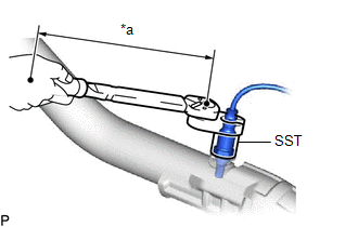
| *a | Torque Wrench Fulcrum Length |
HINT:
Perform "Inspection After Repairs" after replacing the air fuel ratio sensor.
Click here
(a) Using SST, install the heated oxygen sensor to the front exhaust pipe sub-assembly.
SST: 09224-00011
Torque:
Specified tightening torque
44 N*m (449 kgf*cm, 32 ft.*lbf)
NOTICE:
Replace with a new part if it is dropped or if it receives a strong impact.
HINT:
-
Calculate the torque wrench reading when changing the fulcrum length of the torque wrench.
Click here
- When using SST (fulcrum length of 30 mm (1.18 in.)) + torque wrench (fulcrum length of 180 mm (7.09 in.)): 37.7 N*m (384 kgf*cm, 28 ft.*lbf)
(b) Connect the heated oxygen sensor connector.
2. INSTALL FRONT EXHAUST PIPE SUB-ASSEMBLY
Click here
3. INSPECT FOR EXHAUST GAS LEAK
Click here
READ NEXT:
 Ignition Coil And Spark Plug
ComponentsCOMPONENTS ILLUSTRATION *1 IGNITION COIL ASSEMBLY *2 NO. 1 ENGINE COVER SUB-ASSEMBLY *3 SPARK PLUG - - N*m (kgf*cm, ft.*lbf) : Specified torque - - Remova
Parts Location
PARTS LOCATION ILLUSTRATION *1 IGNITION COIL ASSEMBLY *2 ECM *3 NO. 1 ENGINE ROOM RELAY BLOCK LH - IGN FUSE *4 SPARK PLUG
SEE MORE:
Inspection
INSPECTION PROCEDURE 1. INSPECT AIR FUEL RATIO SENSOR (a) Measure the resistance according to the value(s) in the table below. Standard Resistance: Tester Connection Condition Specified Condition 1 (HA1A) - 2 (+B) 20°C (68°F) 1.6 to 3.2 Ω If the result is not as specified, r
Problem Symptoms Table
PROBLEM SYMPTOMS TABLE NOTICE:
Recognition code registration is necessary when replacing the main body ECU (multiplex network body ECU).
If the main body ECU (multiplex network body ECU) is replaced, refer to Registration.
Click here HINT:
Use the table below to help determine the cau
