Lexus NX: Ignition Coil And Spark Plug
Components
COMPONENTS
ILLUSTRATION
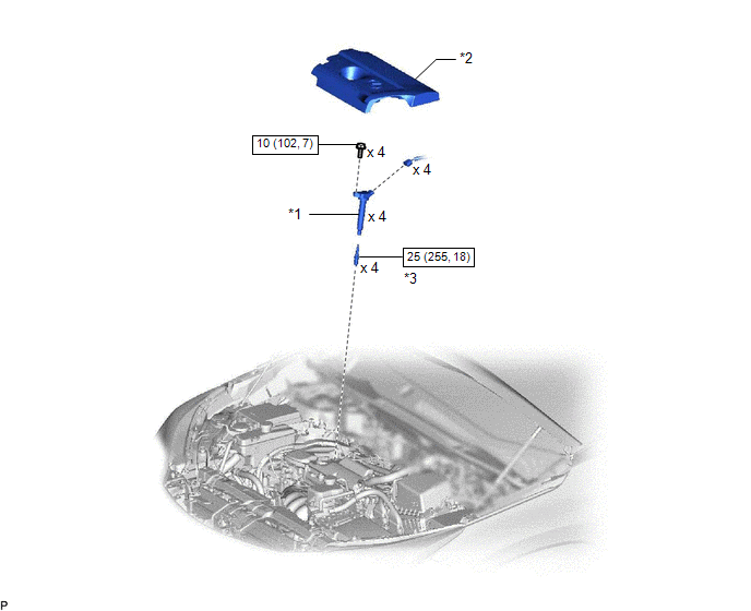
| *1 | IGNITION COIL ASSEMBLY | *2 | NO. 1 ENGINE COVER SUB-ASSEMBLY |
| *3 | SPARK PLUG | - | - |
.png) | N*m (kgf*cm, ft.*lbf) : Specified torque | - | - |
Removal
REMOVAL
PROCEDURE
1. REMOVE NO. 1 ENGINE COVER SUB-ASSEMBLY
Click here .gif)
2. REMOVE IGNITION COIL ASSEMBLY
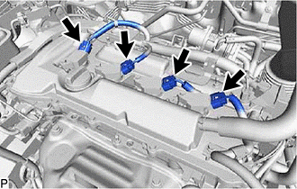
| (a) Disconnect the 4 ignition coil assembly connectors. |
|
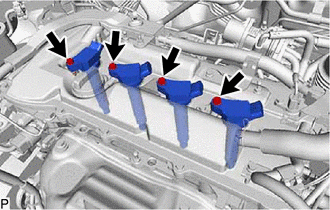
| (b) Remove the 4 bolts and 4 ignition coil assemblies. NOTICE: Replace with a new part if it is dropped or if it receives a strong impact. |
|
3. REMOVE SPARK PLUG
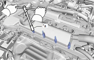
| (a) Using a 16 mm spark plug wrench, remove the 4 spark plugs. NOTICE: Replace with a new part if it is dropped or if it receives a strong impact. |
|
Installation
INSTALLATION
CAUTION / NOTICE / HINT
HINT:
Perform "Inspection After Repairs" after replacing the ignition coil assembly or the spark plug.
Click here .gif)
PROCEDURE
1. INSTALL SPARK PLUG
HINT:
Perform "Inspection After Repairs" after replacing the spark plug.
Click here
(a) Using a 16 mm spark plug wrench, install the 4 spark plugs.
Torque:
25 N·m {255 kgf·cm, 18 ft·lbf}
NOTICE:
Replace with a new part if it is dropped or if it receives a strong impact.
2. INSTALL IGNITION COIL ASSEMBLY
HINT:
Perform "Inspection After Repairs" after replacing the ignition coil assembly.
Click here
(a) Install the 4 ignition coil assemblies with the 4 bolts.
Torque:
10 N·m {102 kgf·cm, 7 ft·lbf}
NOTICE:
Replace with a new part if it is dropped or if it receives a strong impact.
(b) Connect the 4 ignition coil assembly connectors.
3. INSTALL NO. 1 ENGINE COVER SUB-ASSEMBLY
Click here
READ NEXT:
 Parts Location
PARTS LOCATION ILLUSTRATION *1 IGNITION COIL ASSEMBLY *2 ECM *3 NO. 1 ENGINE ROOM RELAY BLOCK LH - IGN FUSE *4 SPARK PLUG
System Diagram
SYSTEM DIAGRAM
SEE MORE:
Removal
REMOVAL PROCEDURE 1. REMOVE DOOR SCUFF PLATE ASSEMBLY LH Click here 2. REMOVE COWL SIDE TRIM BOARD LH Click here 3. REMOVE INSTRUMENT SIDE PANEL LH Click here 4. REMOVE NO. 1 INSTRUMENT PANEL SAFETY PAD SUB-ASSEMBLY Click here 5. REMOVE REAR CONSOLE ARMREST ASSEMBLY Click here
A/F Sensor Slow Response - Rich to Lean Bank 1 Sensor 1 (P014C,P014D,P015A,P015B)
DESCRIPTION Refer to DTC P2195. Click here DTC No. Detection Item DTC Detection Condition Trouble Area MIL Memory P014C A/F Sensor Slow Response - Rich to Lean Bank 1 Sensor 1 The "Rich to Lean response rate deterioration level*" value is standard or less (2 trip detection log
