Lexus NX: High Beam Headlight Circuit
DESCRIPTION
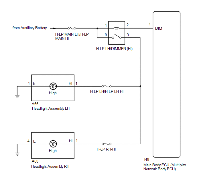
The main body ECU (multiplex network body ECU) controls the high beam headlights.
WIRING DIAGRAM
CAUTION / NOTICE / HINT
NOTICE:
- Inspect the fuses for circuits related to this system before performing the following procedure.
- Recognition code registration is necessary when replacing the main body ECU (multiplex network body ECU).
- If the main body ECU (multiplex network body ECU) is replaced, refer to Registration.
PROCEDURE
| 1. | PERFORM ACTIVE TEST USING TECHSTREAM (HEADLIGHT HI) |
(a) Using the Techstream, perform the Active Test.
Click here .gif)
| Tester Display | Measurement Item | Control Range | Diagnostic Note |
|---|---|---|---|
| Head Light Hi | Headlight dimmer relay | ON or OFF | - |
| Tester Display |
|---|
| Head Light Hi |
OK:
Headlight relay operates. (Hi beam headlights illuminate with the appropriate brightness.)
| OK | .gif) | PROCEED TO NEXT SUSPECTED AREA SHOWN IN PROBLEM SYMPTOMS TABLE |
|
.gif)
| 2. | CHECK HEADLIGHT DIMMER RELAY (H-LP LH/DIMMER [HI]) |
(a) Remove the headlight dimmer relay (H-LP LH/DIMMER [HI]) from the engine room relay block.
(b) Inspect the headlight dimmer relay (H-LP LH/DIMMER [HI]).
| NG | | REPLACE HEADLIGHT DIMMER RELAY (H-LP LH/DIMMER [HI]) |
|
| 3. | CHECK HARNESS AND CONNECTOR (H-LP LH/DIMMER [HI] - BATTERY) |
| (a) Remove the headlight dimmer relay (H-LP LH/DIMMER [HI]) from the engine room relay block. |
|
.png)
(b) Measure the voltage according to the value(s) in the table below.
Standard Voltage:
| Tester Connection | Condition | Specified Condition |
|---|---|---|
| Relay terminal 5 - Body ground | Power switch off | 11 to 14 V |
| Relay terminal 1 - Body ground | Always | 11 to 14 V |
| NG | | REPAIR OR REPLACE HARNESS OR CONNECTOR |
|
| 4. | CHECK HARNESS AND CONNECTOR (H-LP LH/DIMMER [HI] - HEADLIGHT ASSEMBLY) |
- *1: for LH
- *2: for RH
(a) Remove the headlight dimmer relay (H-LP LH/DIMMER [HI]) from the engine room relay block.
(b) Disconnect the A66*1 and A68*2 headlight assembly connector.
(c) Measure the resistance according to the value(s) in the table below.
Standard Resistance:
for LH
| Tester Connection | Condition | Specified Condition |
|---|---|---|
| Relay terminal 3 - A66-1 (HI) | Always | Below 1 Ω |
| Headlight relay terminal 3 - Body ground | Always | 10 kΩ or higher |
for RH
| Tester Connection | Condition | Specified Condition |
|---|---|---|
| Relay terminal 3 - A68-1 (HI) | Always | Below 1 Ω |
| Headlight relay terminal 3 - Body ground | Always | 10 kΩ or higher |
| NG | | REPAIR OR REPLACE HARNESS OR CONNECTOR |
|
| 5. | CHECK HARNESS AND CONNECTOR (H-LP LH/DIMMER [HI] - MAIN BODY ECU [MULTIPLEX NETWORK BODY ECU]) |
(a) Remove the headlight dimmer relay (H-LP LH/DIMMER [HI]) from the engine room relay block.
(b) Disconnect the I46 main body ECU (multiplex network body ECU) connector.
(c) Measure the resistance according to the value(s) in the table below.
Standard Resistance:
| Tester Connection | Condition | Specified Condition |
|---|---|---|
| Relay terminal 2 - I46-1 (DIM) | Always | Below 1 Ω |
| Relay terminal 2 or I46-1 (DIM) - Body ground | Always | 10 kΩ or higher |
| OK | | REPLACE MAIN BODY ECU (MULTIPLEX NETWORK BODY ECU) |
| NG | | REPAIR OR REPLACE HARNESS OR CONNECTOR |
READ NEXT:
 Precaution
PRECAUTION PRECAUTION FOR REPLACEMENT (a) Always prepare a new bulb for immediate replacement. While replacing a bulb, the lens may attract dust and moisture if removed from the vehicle for a long tim
Parts Location
PARTS LOCATION ILLUSTRATION *1 FRONT DOOR COURTESY LIGHT SWITCH ASSEMBLY LH *2 SHIFT LEVER POSITION SENSOR *3 SIDE TURN SIGNAL LIGHT ASSEMBLY LH *4 SIDE TURN SIGNAL LIGHT ASSEMBLY
SEE MORE:
Installation
INSTALLATION PROCEDURE 1. INSTALL METER MIRROR SUB-ASSEMBLY (HEADUP DISPLAY) (a) Install the meter mirror sub-assembly (headup display) with the 4 screws. *a Screw *b Connector (b) Connect the connector. 2. INSTALL NO. 1 HEATER TO REGISTER DUCT SUB-ASSEMBLY (a) Insta
Parts Location
PARTS LOCATION ILLUSTRATION *1 FORWARD RECOGNITION CAMERA *2 BRAKE BOOSTER WITH MASTER CYLINDER ASSEMBLY - SKID CONTROL ECU *3 MILLIMETER WAVE RADAR SENSOR ASSEMBLY - - ILLUSTRATION *1 STEERING SENSOR *2 COMBINATION METER ASSEMBLY *3 MAIN BODY ECU (MULTIPLEX NE
